Page 152 - Satellite Communications, Fourth Edition
P. 152

132  Chapter Five

                                                         Minor
                                                         axis


                                         E V                                   E' V


                                                                       E'
                               E
                                               c                                        c
                                   τ                                       τ'


                                                                         E' H
                                E H
                                              Major
                                              axis
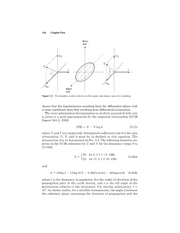
                              Figure 5.13 Polarization vector relative to the major and minor axes of a raindrop.


                              shown that the depolarization resulting from the differential phase shift
                              is more significant than that resulting from differential attenuation.
                                The cross-polarization discrimination in decibels associated with rain
                              is given to a good approximation by the empirical relationship (CCIR
                              Report 564-2, 1982)
                                                     XPD   U   V log A                   (5.21)

                              where U and V are empirically determined coefficients and A is the rain
                              attenuation. U, V,and A must be in decibels in this equation. The
                              attenuation A is as determined in Sec. 4.4. The following formulas are
                              given in the CCIR reference for U and V for the frequency range 8 to
                              35 GHz:

                                                         20   for 8   f   15   GHz
                                                   V   e                                (5.22a)
                                                         23     for 15   f   35   GHz

                              and

                                   U 5 30 log f   10 log (0.5   0.4697 cos 4 )   40 log(cos 
)  (5.22b)

                              where f is the frequency in gigahertz, q is the angle of elevation of the
                              propagation path at the earth station, and t is the tilt angle of the
                              polarization relative to the horizontal. For circular polarization t
                              45°. As shown earlier, for a satellite transmission, the angle ξ between
                              the reference plane containing the direction of propagation and the
   147   148   149   150   151   152   153   154   155   156   157