
Page 224 - Satellite Communications, Fourth Edition
P. 224
204 Chapter Seven
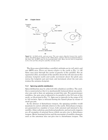
Figure 7.4 (a) Roll, pitch, and yaw axes. The yaw axis is directed toward the earth’s
center, the pitch axis is normal to the orbital plane, and the roll axis is perpendicular to
the other two. (b) RPY axes for the geostationary orbit. Here, the roll axis is tangential
to the orbit and lies along the satellite velocity vector.
The three axes which define a satellite’s attitude are its roll, pitch,and
yaw (RPY) axes. These are shown relative to the earth in Fig. 7.4. All
three axes pass through the center of gravity of the satellite. For an
equatorial orbit, movement of the satellite about the roll axis moves the
antenna footprint north and south; movement about the pitch axis
moves the footprint east and west; and movement about the yaw axis
rotates the antenna footprint.
7.3.1 Spinning satellite stabilization
Spin stabilization may be achieved with cylindrical satellites. The satel-
lite is constructed so that it is mechanically balanced about one partic-
ular axis and is then set spinning around this axis. For geostationary
satellites, the spin axis is adjusted to be parallel to the N-S axis of the
earth, as illustrated in Fig. 7.5. Spin rate is typically in the range of 50
to 100 rev/min. Spin is initiated during the launch phase by means of
small gas jets.
In the absence of disturbance torques, the spinning satellite would
maintain its correct attitude relative to the earth. Disturbance torques
are generated in a number of ways, both external and internal to the
satellite. Solar radiation, gravitational gradients, and meteorite impacts
are all examples of external forces which can give rise to disturbance
torques. Motor-bearing friction and the movement of satellite elements
such as the antennas also can give rise to disturbance torques. The