
Page 235 - Satellite Communications, Fourth Edition
P. 235
The Space Segment 215
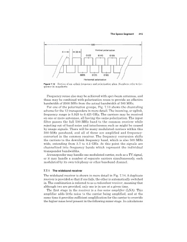
Figure 7.12 Section of an uplink frequency and polarization plan. Numbers refer to fre-
quency in megahertz.
Frequency reuse also may be achieved with spot-beam antennas, and
these may be combined with polarization reuse to provide an effective
bandwidth of 2000 MHz from the actual bandwidth of 500 MHz.
For one of the polarization groups, Fig. 7.13 shows the channeling
scheme for the 12 transponders in more detail. The incoming, or uplink,
frequency range is 5.925 to 6.425 GHz. The carriers may be received
on one or more antennas, all having the same polarization. The input
filter passes the full 500-MHz band to the common receiver while
rejecting out-of-band noise and interference such as might be caused
by image signals. There will be many modulated carriers within this
500-MHz passband, and all of these are amplified and frequency-
converted in the common receiver. The frequency conversion shifts
the carriers to the downlink frequency band, which is also 500 MHz
wide, extending from 3.7 to 4.2 GHz. At this point the signals are
channelized into frequency bands which represent the individual
transponder bandwidths.
A transponder may handle one modulated carrier, such as a TV signal,
or it may handle a number of separate carriers simultaneously, each
modulated by its own telephony or other baseband channel.
7.7.1 The wideband receiver
The wideband receiver is shown in more detail in Fig. 7.14. A duplicate
receiver is provided so that if one fails, the other is automatically switched
in. The combination is referred to as a redundant receiver, meaning that
although two are provided, only one is in use at a given time.
The first stage in the receiver is a low-noise amplifier (LNA). This
amplifier adds little noise to the carrier being amplified, and at the
same time it provides sufficient amplification for the carrier to override
the higher noise level present in the following mixer stage. In calculations