
Page 24 - Satellite Communications, Fourth Edition
P. 24
4 Chapter One
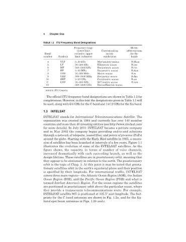
TABLE 1.2 ITU Frequency Band Designations
Frequency range Metric
(lower limit Corresponding abbreviations
Band exclusive, upper metric for the
number Symbols limit inclusive) subdivision bands
4 VLF 3–30 kHz Myriametric waves B.Mam
5 LF 30–300 kHz Kilometric waves B.km
6 MF 300–3000 kHz Hectometric waves B.hm
7 HF 3–30 MHz Decametric waves B.dam
8 VHF 30–300 MHz Metric waves B.m
9 UHF 300–3000 MHz Decimetric waves B.dm
10 SHF 3–30 GHz Centimetric waves B.cm
11 EHF 30–300 GHz Millimetric waves B.mm
12 300–3000 GHz Decimillimetric waves
SOURCE: ITU Geneva.
The official ITU frequency band designations are shown in Table 1.2 for
completeness. However, in this text the designations given in Table 1.1 will
be used, along with 6/4 GHz for the C band and 14/12 GHz for the Ku band.
1.3 INTELSAT
INTELSAT stands for International Telecommunications Satellite. The
organization was created in 1964 and currently has over 140 member
countries and more than 40 investing entities (see http://www.intelsat.com/
for more details). In July 2001 INTELSAT became a private company
and in May 2002 the company began providing end-to-end solutions
through a network of teleports, leased fiber, and points of presence (PoPs)
around the globe. Starting with the Early Bird satellite in 1965, a succes-
sion of satellites has been launched at intervals of a few years. Figure 1.1
illustrates the evolution of some of the INTELSAT satellites. As the
figure shows, the capacity, in terms of number of voice channels,
increased dramatically with each succeeding launch, as well as the
design lifetime. These satellites are in geostationary orbit, meaning that
they appear to be stationary in relation to the earth. The geostationary
orbit is the topic of Chap. 3. At this point it may be noted that geosta-
tionary satellites orbit in the earth’s equatorial plane and their position
is specified by their longitude. For international traffic, INTELSAT
covers three main regions—the Atlantic Ocean Region (AOR), the Indian
Ocean Region (IOR), and the Pacific Ocean Region (POR) and what is
termed Intelsat America’s Region. For the ocean regions the satellites
are positioned in geostationary orbit above the particular ocean, where
they provide a transoceanic telecommunications route. For example,
INTELSAT satellite 905 is positioned at 335.5° east longitude. The foot-
prints for the C-band antennas are shown in Fig. 1.2a, and for the Ku-
band spot beam antennas in Figs. 1.2b and c.