
Page 253 - Satellite Communications, Fourth Edition
P. 253
The Space Segment 233
1B 1
1A 2
3A 3
3B 4
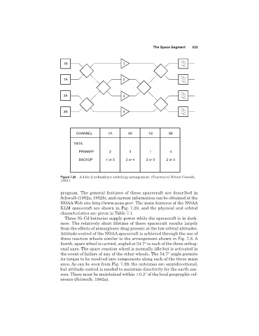
CHANNEL 1A 3A 1B 3B
TWTA
PRIMARY 2 3 1 4
BACKUP 1 or 3 2 or 4 2 or 3 2 or 3
Figure 7.28 A 4-for-2 redundancy switching arrangement. (Courtesy of Telesat Canada,
1983.)
program. The general features of these spacecraft are described in
Schwalb (1982a, 1982b), and current information can be obtained at the
NOAA Web site http://www.noaa.gov/. The main features of the NOAA
KLM spacecraft are shown in Fig. 7.29, and the physical and orbital
characteristics are given in Table 7.1.
Three Ni-Cd batteries supply power while the spacecraft is in dark-
ness. The relatively short lifetime of these spacecraft results largely
from the effects of atmospheric drag present at the low orbital altitudes.
Attitude control of the NOAA spacecraft is achieved through the use of
three reaction wheels similar to the arrangement shown in Fig. 7.8. A
fourth, spare wheel is carried, angled at 54.7° to each of the three orthog-
onal axes. The spare reaction wheel is normally idle but is activated in
the event of failure of any of the other wheels. The 54.7° angle permits
its torque to be resolved into components along each of the three main
axes. As can be seen from Fig. 7.29, the antennas are omnidirectional,
but attitude control is needed to maintain directivity for the earth sen-
sors. These must be maintained within 0.2° of the local geographic ref-
erence (Schwalb, 1982a).