
Page 304 - Satellite Communications, Fourth Edition
P. 304
284 Chapter Ten
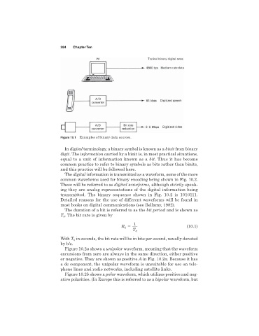
Figure 10.1 Examples of binary data sources.
In digital terminology, a binary symbol is known as a binit from binary
digit.The information carried by a binit is, in most practical situations,
equal to a unit of information known as a bit. Thus it has become
common practice to refer to binary symbols as bits rather than binits,
and this practice will be followed here.
The digital information is transmitted as a waveform, some of the more
common waveforms used for binary encoding being shown in Fig. 10.2.
These will be referred to as digital waveforms, although strictly speak-
ing they are analog representations of the digital information being
transmitted. The binary sequence shown in Fig. 10.2 is 1010111.
Detailed reasons for the use of different waveforms will be found in
most books on digital communications (see Bellamy, 1982).
The duration of a bit is referred to as the bit period and is shown as
T . The bit rate is given by
b
1
(10.1)
R b
T b
in seconds, the bit rate will be in bits per second, usually denoted
With T b
by b/s.
Figure 10.2a shows a unipolar waveform, meaning that the waveform
excursions from zero are always in the same direction, either positive
or negative. They are shown as positive A in Fig. 10.2a. Because it has
a dc component, the unipolar waveform is unsuitable for use on tele-
phone lines and radio networks, including satellite links.
Figure 10.2b shows a polar waveform, which utilizes positive and neg-
ative polarities. (In Europe this is referred to as a bipolar waveform, but