
Page 144 - Schaum's Outline of Theory and Problems of Applied Physics
P. 144
CHAP. 11] EQUILIBRIUM 129
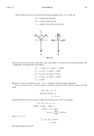
The forces that act on the box are shown in the free-body diagram of Fig. 11-1(a). They are
T 1 = tension in left-hand rope
T 2 = tension in right-hand rope
w = weight of box, which acts downward
Fig. 11-1
Since the forces all lie in a plane, we need only x and y axes. In Fig. 11-1(b) the forces are resolved into their x and
y components, whose magnitudes are as follows:
◦
T 1x =−T 1 sin θ 1 =−T 1 sin 40 =−0.643T 1
◦
T 1y = T 1 cos θ 1 = T 1 cos 40 = 0.766T 1
◦
T 2x = T 2 sin θ 2 = T 2 sin 40 = 0.643T 2
◦
T 2y = T 2 cos θ 2 = T 2 cos 40 = 0.766T 2
w =−100 N
Because T 1x and w are, respectively, in the −x and −y directions, both have negative magnitudes.
Now we are ready for step 3. First we add the x components of the forces and set the sum equal to zero. This
yields
F x = T 1x + T 2x = 0
−0.643T 1 + 0.643T 2 = 0
T 1 = T 2 = T
Evidently the tensions in the two ropes are equal. Next we do the same for the y components:
F y = T 1y + T 2y + w = 0
0.766T 1 + 0.766T 2 − 100 N = 0
0.766(T 1 + T 2 ) = 100 N
100 N
T 1 + T 2 = = 130.5N
0.766
Since T 1 = T 2 = T ,
T 1 + T 2 = 2T = 130.5N
T = 65 N
The tension in each rope is 65 N.