
Page 305 - Schaum's Outline of Theory and Problems of Applied Physics
P. 305
290 DIRECT-CURRENTCIRCUITS [CHAP. 25
(b) The voltage across the 5- bulb is
V 1 = IR 1 = (0.8A)(5 ) = 4V
and that across the 10- bulb is
V 2 = IR 2 = (0.8A)(10 ) = 8V
As a check, we note that the total voltage is
V = V 1 + V 2 = 4V + 8V = 12 V
which equals the impressed voltage of 12 V, as it should.
(c) P 1 = IV 1 = (0.8A)(4V) = 3.2W P 2 = IV 2 = (0.8A)(8V) = 6.4W
The total powers is the sum of the powers dissipated by each bulb:
P = P 1 + P 2 = 3.2W + 6.4W = 9.6W
As a check, we can calculate the power dissipated by the equivalent resistance of 15 :
2
2
2
P = I R = (0.8A) (15 ) = (0.64 A )(15 ) = 9.6W
SOLVED PROBLEM 25.5
A 2000- and a 5000- resistor are in series as part of a larger circuit. A voltmeter shows the potential
difference across the 2000- resistor to be 2 V. Find (a) the current in each resistor and (b) the potential
difference across the 5000- resistor.
(a) The current in the 2000- resistor is
V 1 2V
I = = = 0.001 A
R 1 200
This current flows through the other resistor as well.
(b) The potential difference across R 2 is
V 2 = IR 2 = (0.001 A)(5000 ) = 5V
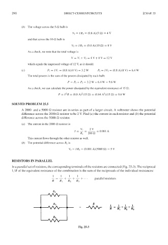
RESISTORS IN PARALLEL
In a parallel set of resistors, the corresponding terminals of the resistors are connected (Fig. 25-3). The reciprocal
1/R of the equivalent resistance of the combination is the sum of the reciprocals of the individual resistances:
1 1 1 1
= + + +· · · parallel resistors
R R 1 R 2 R 3
Fig. 25-3