
Page 106 - Sensing, Intelligence, Motion : How Robots and Humans Move in an Unstructured World
P. 106
UNIVERSAL LOWER BOUND FOR THE PATH PLANNING PROBLEM 81
We will use the following scheme to design the required scene (called the
resultant scene). The scene is built in two stages. At the first stage, a virtual
obstacle is introduced. Parts of this obstacle or the whole of it, but not more, will
eventually become, when the second stage is completed, the actual obstacle(s)
of the resultant scene.
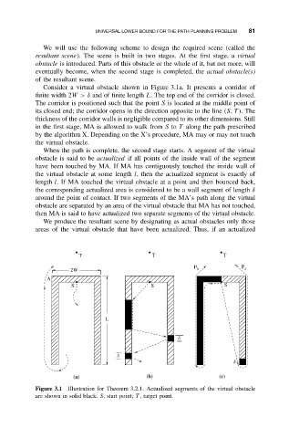
Consider a virtual obstacle shown in Figure 3.1a. It presents a corridor of
finite width 2W> δ and of finite length L. The top end of the corridor is closed.
The corridor is positioned such that the point S is located at the middle point of
its closed end; the corridor opens in the direction opposite to the line (S, T ).The
thickness of the corridor walls is negligible compared to its other dimensions. Still
in the first stage, MA is allowed to walk from S to T along the path prescribed
by the algorithm X. Depending on the X’s procedure, MA may or may not touch
the virtual obstacle.
When the path is complete, the second stage starts. A segment of the virtual
obstacle is said to be actualized if all points of the inside wall of the segment
have been touched by MA. If MA has contiguously touched the inside wall of
the virtual obstacle at some length l, then the actualized segment is exactly of
length l. If MA touched the virtual obstacle at a point and then bounced back,
the corresponding actualized area is considered to be a wall segment of length δ
around the point of contact. If two segments of the MA’s path along the virtual
obstacle are separated by an area of the virtual obstacle that MA has not touched,
then MA is said to have actualized two separate segments of the virtual obstacle.
We produce the resultant scene by designating as actual obstacles only those
areas of the virtual obstacle that have been actualized. Thus, if an actualized
T T T
P
P b a
2W
A
S S S
L
d
d
d
(a) (b) (c)
Figure 3.1 Illustration for Theorem 3.2.1. Actualized segments of the virtual obstacle
are shown in solid black. S, start point; T , target point.