
Page 348 - Sensing, Intelligence, Motion : How Robots and Humans Move in an Unstructured World
P. 348
THREE-LINK XXP ARM MANIPULATORS 323
T b
T
O 1 p
g 1
O 2 O 2
p
a a
S
g 4 g 3
O 1 O 1
T b T
(a)
T
g 2
g 1
S O 2 S
III
II
O 1 I O 1
g 3 p 2
g 3
O 1 O 1
T T
p 1
IV p 3
V
g 1
g 2
S
(b)
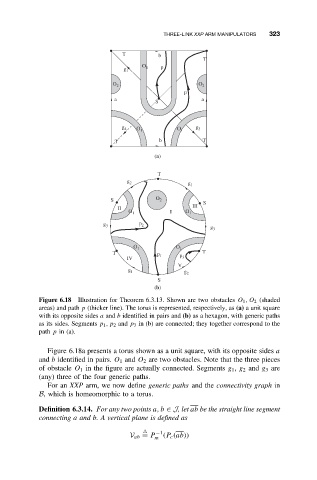
Figure 6.18 Illustration for Theorem 6.3.13. Shown are two obstacles O 1 ,O 2 (shaded
areas) and path p (thicker line). The torus is represented, respectively, as (a) a unit square
with its opposite sides a and b identified in pairs and (b) as a hexagon, with generic paths
as its sides. Segments p 1 ,p 2 and p 3 in (b) are connected; they together correspond to the
path p in (a).
Figure 6.18a presents a torus shown as a unit square, with its opposite sides a
and b identified in pairs. O 1 and O 2 are two obstacles. Note that the three pieces
of obstacle O 1 in the figure are actually connected. Segments g 1 , g 2 and g 3 are
(any) three of the four generic paths.
For an XXP arm, we now define generic paths and the connectivity graph in
B, which is homeomorphic to a torus.
Definition 6.3.14. For any two points a, b ∈ J,let ab be the straight line segment
connecting a and b. A vertical plane is defined as
−1
V ab = P m (P c (ab))