
Page 431 - Sensing, Intelligence, Motion : How Robots and Humans Move in an Unstructured World
P. 431
406 SENSITIVE SKIN—DESIGNING AN ALL-SENSITIVE ROBOT ARM MANIPULATOR
IC2
IC1a
Signal in
12 identical Out
inputs
12 12
Address in
Bit 0 - 3 Receive
signal
-15V Sensitive
IC1b IC1c Skin
IC1d
Transmit
Bit 7
signal
IC8a Bit 4-7 IC3 & IC4
Out Set Address in 25
Clk D
IC7 IC5a Q IC4
Rst Ck inhibit
Rst Q
IC3
inhibit
Analog
sensor
signal
+10V
Sensor IC8b IC8c
select C
Sensor C IC6a R C
-Tr Q IC6b
Interface Reset
MF +Tr
Reset
+10V
Modulation
frequency Set S1
D Q
IC5b
Ck Q
Rst
Notation:
- Single signal - n signal lines S1 - Modulation frequency
line n select
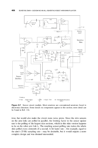
Figure 8.5 Sensor circuit module. Most notations are conventional notations found in
electronics literature. Some details on components appear in this section; more detail can
be found in Ref. 134.
time, but would also make the circuit more noise prone. Since the skin sensors
on the arm links are polled in parallel, the limiting factor in the sensor update
rate is the polling of the largest skin sections, which in this skin version happens
to be on the robot arm link l 3 . The resulting sensor polling rate makes the whole
skin polled every sixteenth of a second. A bit faster rate—for example, equal to
the arm’s 25-Hz sampling rate—may be desirable, but it would require a more
complex design and was deemed unessential.