
Page 199 -
P. 199
182 Chapter 7 Design and implementation
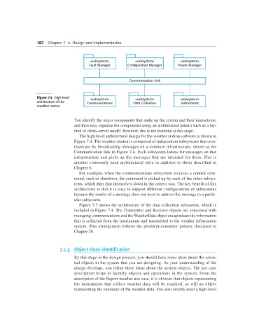
«subsystem» «subsystem» «subsystem»
Fault Manager Configuration Manager Power Manager
Communication Link
Figure 7.4 High-level «subsystem» «subsystem» «subsystem»
architecture of the Communications Data Collection Instruments
weather station
You identify the major components that make up the system and their interactions,
and then may organize the components using an architectural pattern such as a lay-
ered or client–server model. However, this is not essential at this stage.
The high-level architectural design for the weather station software is shown in
Figure 7.4. The weather station is composed of independent subsystems that com-
municate by broadcasting messages on a common infrastructure, shown as the
Communication link in Figure 7.4. Each subsystem listens for messages on that
infrastructure and picks up the messages that are intended for them. This is
another commonly used architectural style in addition to those described in
Chapter 6.
For example, when the communications subsystem receives a control com-
mand, such as shutdown, the command is picked up by each of the other subsys-
tems, which then shut themselves down in the correct way. The key benefit of this
architecture is that it is easy to support different configurations of subsystems
because the sender of a message does not need to address the message to a partic-
ular subsystem.
Figure 7.5 shows the architecture of the data collection subsystem, which is
included in Figure 7.4. The Transmitter and Receiver objects are concerned with
managing communications and the WeatherData object encapsulates the information
that is collected from the instruments and transmitted to the weather information
system. This arrangement follows the producer-consumer pattern, discussed in
Chapter 20.
7.1.3 Object class identification
By this stage in the design process, you should have some ideas about the essen-
tial objects in the system that you are designing. As your understanding of the
design develops, you refine these ideas about the system objects. The use case
description helps to identify objects and operations in the system. From the
description of the Report weather use case, it is obvious that objects representing
the instruments that collect weather data will be required, as will an object
representing the summary of the weather data. You also usually need a high-level