
Page 36 -
P. 36
1.3 Case studies 19
Insulin Reservoir
Needle
Assembly Pump Clock
Sensor Controller Alarm
Display1 Display2
Figure 1.4 Insulin Power Supply
pump hardware
Blood Analyze Sensor Blood Compute Insulin
Sensor Reading Sugar Insulin Log
Insulin
Dose
Insulin Control Insulin Pump Compute Pump Log Dose
Pump Pump Data Commands
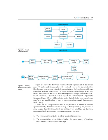
Figure 1.4 shows the hardware components and organization of the insulin
Figure 1.5 Activity
model of the insulin pump. To understand the examples in this book, all you need to know is that the
pump blood sensor measures the electrical conductivity of the blood under different
conditions and that these values can be related to the blood sugar level. The
insulin pump delivers one unit of insulin in response to a single pulse from a con-
troller. Therefore, to deliver 10 units of insulin, the controller sends 10 pulses to
the pump. Figure 1.5 is a UML activity model that illustrates how the software
transforms an input blood sugar level to a sequence of commands that drive the
insulin pump.
Clearly, this is a safety-critical system. If the pump fails to operate or does not
operate correctly, then the user’s health may be damaged or they may fall into a
coma because their blood sugar levels are too high or too low. There are, therefore,
two essential high-level requirements that this system must meet:
1. The system shall be available to deliver insulin when required.
2. The system shall perform reliably and deliver the correct amount of insulin to
counteract the current level of blood sugar.