
Page 148 -
P. 148
CHAPTER 5 SOFTWARE PROJECT PLANNING 119
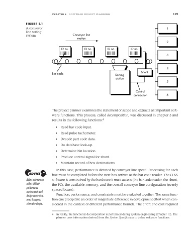
FIGURE 5.1
A conveyor 1
line sorting
system Conveyor line
motion
2
ID no. ID no. ID no. ID no.
3
4
Shunt
Bar code
Sorting
station
5
Control
connection 6
The project planner examines the statement of scope and extracts all important soft-
ware functions. This process, called decomposition, was discussed in Chapter 3 and
results in the following functions: 4
• Read bar code input.
• Read pulse tachometer.
• Decode part code data.
• Do database look-up.
• Determine bin location.
• Produce control signal for shunt.
• Maintain record of box destinations.
In this case, performance is dictated by conveyor line speed. Processing for each
box must be completed before the next box arrives at the bar code reader. The CLSS
Adjust estimates to software is constrained by the hardware it must access (the bar code reader, the shunt,
reflect difficult the PC), the available memory, and the overall conveyor line configuration (evenly
performance
requirements and spaced boxes).
design constraints, Function, performance, and constraints must be evaluated together. The same func-
even if scope is tion can precipitate an order of magnitude difference in development effort when con-
otherwise simple. sidered in the context of different performance bounds. The effort and cost required
4 In reality, the functional decomposition is performed during system engineering (Chapter 10). The
planner uses information derived from the System Specification to define software functions.