
Page 151 - Software and Systems Requirements Engineering in Practice
P. 151
118 S o f t w a r e & S y s t e m s R e q u i r e m e n t s E n g i n e e r i n g : I n P r a c t i c e
5. Do the test cases match (are appropriate) for the related
requirements?
6. Do system-level requirements derive from the components;
e.g., a component must perform the following functions…?
Design Model Initial Construction
When a design model is derived from the analysis model, the
following steps are normally taken:
1. Naming conventions and design standards are identified and
applied.
2. For each major use case in the analysis model, packages are
created in the design model.
3. Use case realizations provide tracing from the requirements
to the design. These realizations are inserted at whatever
level is deemed necessary by the lead architect and quality
assurance. Reports can then be generated showing the
analysis model use case, associated requirements, and
associated components (by tracing from the use case
realization to its associated components).
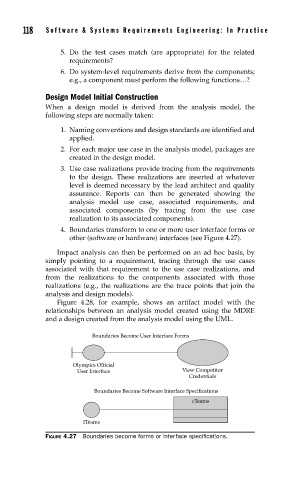
4. Boundaries transform to one or more user interface forms or
other (software or hardware) interfaces (see Figure 4.27).
Impact analysis can then be performed on an ad hoc basis, by
simply pointing to a requirement, tracing through the use cases
associated with that requirement to the use case realizations, and
from the realizations to the components associated with those
realizations (e.g., the realizations are the trace points that join the
analysis and design models).
Figure 4.28, for example, shows an artifact model with the
relationships between an analysis model created using the MDRE
and a design created from the analysis model using the UML.
Boundaries Become User Interface Forms
Olympics Official
User Interface View Competitor
Credentials
Boundaries Become Software Interface Specifications
cTeams
ITeams
FIGURE 4.27 Boundaries become forms or interface specifications.