
Page 104 - Solar Power in Building Design The Engineer's Complete Design Resource
P. 104
74 SOLAR POWER SYSTEM DESIGN CONSIDERATIONS
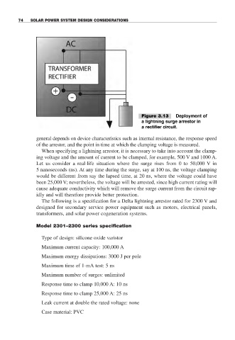
Figure 3.13 Deployment of
a lightning surge arrestor in
a rectifier circuit.
general depends on device characteristics such as internal resistance, the response speed
of the arrestor, and the point in time at which the clamping voltage is measured.
When specifying a lightning arrestor, it is necessary to take into account the clamp-
ing voltage and the amount of current to be clamped, for example, 500 V and 1000 A.
Let us consider a real-life situation where the surge rises from 0 to 50,000 V in
5 nanoseconds (ns). At any time during the surge, say at 100 ns, the voltage clamping
would be different from say the lapsed time, at 20 ns, where the voltage could have
been 25,000 V; nevertheless, the voltage will be arrested, since high current rating will
cause adequate conductivity which will remove the surge current from the circuit rap-
idly and will therefore provide better protection.
The following is a specification for a Delta lightning arrestor rated for 2300 V and
designed for secondary service power equipment such as motors, electrical panels,
transformers, and solar power cogeneration systems.
Model 2301–2300 series specification
Type of design: silicone oxide varistor
Maximum current capacity: 100,000 A
Maximum energy dissipations: 3000 J per pole
Maximum time of 1-mA test: 5 ns
Maximum number of surges: unlimited
Response time to clamp 10,000 A: 10 ns
Response time to clamp 25,000 A: 25 ns
Leak current at double the rated voltage: none
Case material: PVC