
Page 46 - Solar Power in Building Design The Engineer's Complete Design Resource
P. 46
16 SOLAR POWER SYSTEM PHYSICS
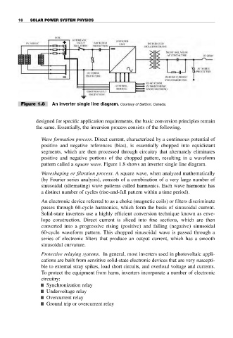
Figure 1.8 An inverter single line diagram. Courtesy of SatCon, Canada.
designed for specific application requirements, the basic conversion principles remain
the same. Essentially, the inversion process consists of the following.
Wave formation process. Direct current, characterized by a continuous potential of
positive and negative references (bias), is essentially chopped into equidistant
segments, which are then processed through circuitry that alternately eliminates
positive and negative portions of the chopped pattern, resulting in a waveform
pattern called a square wave. Figure 1.8 shows an inverter single line diagram.
Waveshaping or filtration process. A square wave, when analyzed mathematically
(by Fourier series analysis), consists of a combination of a very large number of
sinusoidal (alternating) wave patterns called harmonics. Each wave harmonic has
a distinct number of cycles (rise-and-fall pattern within a time period).
An electronic device referred to as a choke (magnetic coils) or filters discriminate
passes through 60-cycle harmonics, which form the basis of sinusoidal current.
Solid-state inverters use a highly efficient conversion technique known as enve-
lope construction. Direct current is sliced into fine sections, which are then
converted into a progressive rising (positive) and falling (negative) sinusoidal
60-cycle waveform pattern. This chopped sinusoidal wave is passed through a
series of electronic filters that produce an output current, which has a smooth
sinusoidal curvature.
Protective relaying systems. In general, most inverters used in photovoltaic appli-
cations are built from sensitive solid-state electronic devices that are very suscepti-
ble to external stray spikes, load short circuits, and overload voltage and currents.
To protect the equipment from harm, inverters incorporate a number of electronic
circuitry:
■ Synchronization relay
■ Undervoltage relay
■ Overcurrent relay
■ Ground trip or overcurrent relay