
Page 250 - Standard Handbook Petroleum Natural Gas Engineering VOLUME2
P. 250
Pressure Transient Testing of Oil and Gas Wells 219
LLI ’
+
[(t
log
)/At]
At
FAULT or NEARBY STRATIFIED LAYERS or LATERAL DECREASE
BOUNDARY FRACTURES w/TIGHT MATRIX IN MOBILITY
I
I
t
E
a
+log -
t +At
At
PLAN VIEW OF RESERVOIR PRESSURE BUILDUP CURVE,
MULTIPLE BOUNDARIES
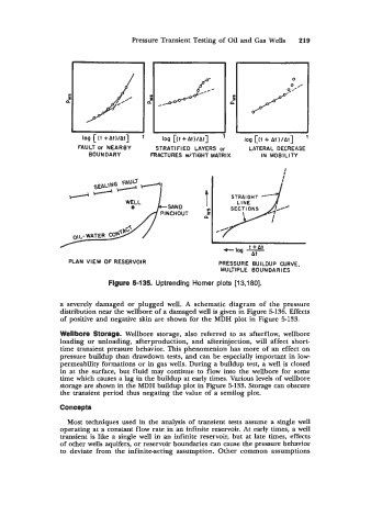
Flgure 5-135. Uptrending Horner plots [13,180].
a severely damaged or plugged well. A schematic diagram of the pressure
distribution near the wellbore of a damaged well is given in Figure 5-136. Effects
of positive and negative skin are shown for the MDH plot in Figure 5-133.
Wellbore Storage. Wellbore storage, also referred to as afterflow, wellbore
loading or unloading, afterproduction, and afterinjection, will affect short-
time transient pressure behavior. This phenomenion has more of an effect on
pressure buildup than drawdown tests, and can be especially important in low-
permeability formations or in gas wells. During a buildup test, a well is closed
in at the surface, but fluid may continue to flow into the wellbore for some
time which causes a lag in the buildup at early times. Various levels of wellbore
storage are shown in the MDH buildup plot in Figure 5-133. Storage can obscure
the transient period thus negating the value of a semilog plot.
Concepts
Most techniques used in the analysis of transient tests assume a single well
operating at a constant flow rate in an infinite reservoir. At early times, a well
transient is like a single well in an infinite reservoir, but at late times, effects
of other wells aquifers, or reservoir boundaries can cause the pressure behavior
to deviate from the infinite-acting assumption. Other common assumptions