
Page 299 - Standard Handbook Petroleum Natural Gas Engineering VOLUME2
P. 299
266 Reservoir Engineering
of pattern will depend on circumstances in a given field. If existing wells were
drilled on square patterns, 5-spots and 9-spots are common, and both yield
similar oil recovery and waterd ratio performance. If the injected fluid is more
mobile than the displacing fluid (which is often the case, especially when oil
viscosity is high), a pattern having more producers than injectors may be desired
to balance the injection and production rates. In cases where the injected fluid
is less mobile or when the formation permeability is low, a pattern having more
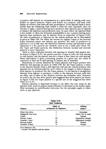
injectors than producers may be desired. From an inspection of Figure 5150,
the ratio of producers to injectors for the various patterns can be determined
as given in Table 5-35. For either the normal (or regular) 5-spot or the inverted
5-spot (inverted means one injector per pattern), the ratio of producers to
injectors is 1:l; in this case, the distinction between normal and inverted is only
important if a few patterns are involved, such as for a small pilot flood. For
the "-spot and Sspot patterns, the distinction between normal and inverted
patterns is more important.
There is often confusion between well spacing (or density) and pattern size.
As shown in Figure 5-151, the pattern area for a 5spot is twice the well spacing
or well density, and the pattern area for a %spot is four times the well spacing.
When information is given concerning patterns of a given size, the reader is
cautioned to find out if well spacing or pattern size is intended.
Dimensions of various distances for hpot patterns and Sspot patterns with
different well spacings are given in Table 5-36. For the 9-spot pattern, s refers
to the shortest distance from a side injection well and the central producer (the
opposite for an inverted pattern), and 1 refers to the longest or lateral distance
from injector to producer. For the 5-spot pattern, 1 is the lateral or straight-line
distance from injector to producer, a refers to the distance between wells that
are alike, and d refers to the distance between the dissimilar wells. Distances
of d and a for the line drive pattern and staggered line drive pattern are shown
in Figure 5-152; the 5-spot pattern is a special case of the staggered line drive
when d/a is 0.5.
Pattern selection is important because it can affect the area swept by the
injected fluid. Areal or pattern sweep efficiency is discussed in the section under
fluid movement in waterflooded reservoirs, but the principles apply to either
water or gas injection.
Table 5-35
Well Patterns
Ratio of
Pattern producers to injectors pattern
Direct line drive 1 Rectangle
Staggered line drive 1 Offset line of wells
5-spot 1 Square
Normal 7-spot 1/2 Equilateral triangle
Inverted 7-spot 2 Equilateral triangle
Normal 9-spot 1 I3 Square
Inverted* 9-spot 3 Square
From Reference 133.
* Inverted One injection well per pattern