
Page 134 - Steam Turbines--Design, Applications, and Rerating by Heinz-Bloch, Murari-Singh
P. 134
Turbine Blade Design Overview 115
The final blade of each row is identical with the normal blades except
for the missing recesses in the T-root. The final blade is always secured
with high-strength fasteners. Thus the spacing of the final blade does
not differ from that of the normal blades.
The inserted, nonshrouded, freestanding blade has been largely dis-
continued in industrial turbine construction.
Guide blades and rotor blades typically have an identical blade pro-
file. This profile is geometrically enlarged by a constant factor so that a
range of geometrically similar blade profiles is created. For all profile
sizes the optimal pitch ratio (pitch/profile chord length) is selected. The
stagger angles of the blade profiles are graded and are equal for all pro-
file sizes. In essence, geometrically similar blade cascades are thus cre-
ated for all profile sizes.
The profile chord length remains constant for the full blade length.
Only a few standardized stagger angles are generally used by a given
manufacturer. The ratio of blade length to mean blade diameter is typ-
ically limited to 0.2. Therefore the pitch at hub and blade tip cannot
deviate too much from the optimal value. At the same time the fan
losses stay within a reasonable range.
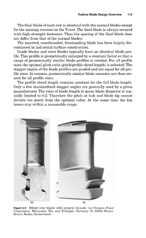
(a) (b)
Figure 6.9 Milled rotor blades with integral shrouds. ((a) Siemens Power
Corporation, Milwaukee, Wis. and Erlangen, Germany (b) ASEA Brown-
Boveri, Baden, Switzerland)