
Page 238 - Steam Turbines--Design, Applications, and Rerating by Heinz-Bloch, Murari-Singh
P. 238
Campbell, Goodman, and SAFE Diagrams for Steam Turbine Blades 217
Figs. 11.31 and 11.32 with the addition of definitions followed in this
write-up. Figure 11.31 is a Campbell diagram with resonance points
(partial). Figure 11.32 is a SAFE diagram (partial) showing the period-
icity every 180° or N/2.
This confirms that the SAFE diagram shows all the resonant points
in a bladed disk structure.
11.9 Summary
■ SAFE diagrams bring in the additional required information about
resonant conditions, namely mode shape and force profile for pack-
eted bladed disk assemblies.
■ A designer does not have to make numerous calculations for
response but only at selected points of concern(s).
■ Interferences on a Campbell diagram are very difficult to show in the
low-speed range while the SAFE diagram retains clarity for every
speed.
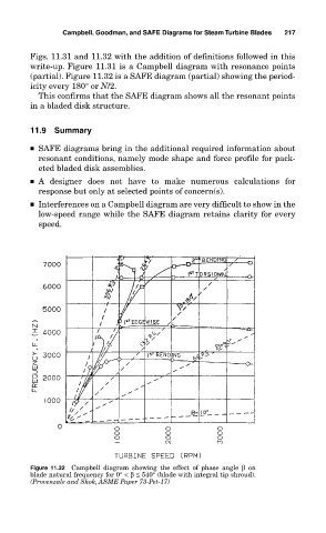
Figure 11.32 Campbell diagram showing the effect of phase angle β on
blade natural frequency for 0°<β≤ 540° (blade with integral tip shroud).
(Provenzale and Skok, ASME Paper 73-Pet-17)