
Page 253 - Steam Turbines--Design, Applications, and Rerating by Heinz-Bloch, Murari-Singh
P. 253
232 Chapter Twelve
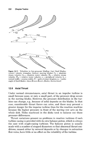
Figure 12.11 Velocities in low-pressure blading: (top) fixed blades;
(center) velocity triangles; (bottom) moving blades; C D = absolute
steam velocity; C W = absolute water velocity; W D = relative steam
velocity; W W = relative water velocity; u = peripheral velocity; b e =
wetted width = erosion width; Tr = path of water droplets; α 1 = outlet
angle of fixed blades. (Asea Brown-Boveri, Baden, Switzerland)
12.6 Axial Thrust
Under normal circumstances, axial thrust in an impulse turbine is
small because none, or only a small part, of the pressure drop occurs
in the moving blades. However, the pressure distribution in the tur-
bine can change, e.g., because of solid deposits on the blades. In that
case, considerable thrust forces can arise, and these may present a
greater danger for the impulse turbine than for the reaction machine
because the higher pressure in front of the moving row acts on the
whole disk. Holes machined in the disks tend to balance out these
pressure differences.
Thrust variations present no problems in reaction turbines if each
turbine casing is provided with its own balance piston, which is always
the case with single-casing turbines. The balance piston is usually
made with a number of stepped diameters so that abnormal thrust con-
ditions, caused either by mineral deposits or by changes in extraction
flow rates, have little or no effect on the reliability of the turbine.