
Page 42 - Steam Turbines--Design, Applications, and Rerating by Heinz-Bloch, Murari-Singh
P. 42
Introduction 23
control system, the lube and hydraulic system, baseplate, and total sys-
tem design, manufacture, and integration.
This design offers maximum factory assembly and testing to ensure
quick and reliable field installation and start-up. Factory packaging
includes the installation and alignment of the fully assembled turbine,
oil system, and gear (if applicable) on a baseplate, and the generator,
compressor, or pump on a separate baseplate, depending on the size of
the unit. All major components are piped for the lube and control oil as
required, steam seal piping, gland leakoff piping, instrumentation, and
control wiring, all within the confines of the baseplate(s). Terminations
consist of conveniently located pipe flanges at the edge of the base and
electrical terminal boxes.
The rugged baseplates used to integrate the set should be designed
to control deflection and stress during a simplified four-point lift. This
type of a lift at the site is most reliable and permits rapid installation
of the package. This base design avoids the use of costly and risky six-
point lifts and would permit a range of customer foundation designs
due to its rigidity.
For units whose overall lengths are compatible with shipping and
manufacturing limitations, a single package including the turbine,
gear (if applicable), and lube oil system module is provided. Otherwise,
two modules are provided, one for the base-mounted turbine and the
other for the lube oil system module. An example of this configuration
is shown in Fig. 1.18. In this case, the lube oil system is supplied on a
separate skid that can be located conveniently near the unit for inter-
connection to the turbine.
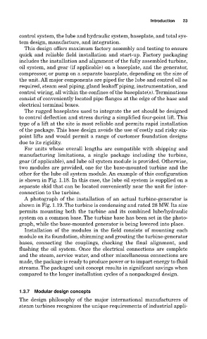
A photograph of the installation of an actual turbine-generator is
shown in Fig. 1.19. The turbine is condensing and rated 28 MW. Its size
permits mounting both the turbine and its combined lube/hydraulic
system on a common base. The turbine base has been set in the photo-
graph, while the base-mounted generator is being lowered into place.
Installation of the modules in the field consists of mounting each
module on its foundation, shimming and grouting the turbine-generator
bases, connecting the couplings, checking the final alignment, and
flushing the oil system. Once the electrical connections are complete
and the steam, service water, and other miscellaneous connections are
made, the package is ready to produce power or to impart energy to fluid
streams. The packaged unit concept results in significant savings when
compared to the longer installation cycles of a nonpackaged design.
1.3.7 Modular design concepts
The design philosophy of the major international manufacturers of
steam turbines recognizes the unique requirements of industrial appli-