
Page 256 - Structural Steel Designers Handbook AISC, AASHTO, AISI, ASTM, and ASCE-07 Design Standards
P. 256
Brockenbrough_Ch05.qxd 9/29/05 5:12 PM Page 5.36
CRITERIA FOR BUILDING DESIGN
5.36 CHAPTER FIVE
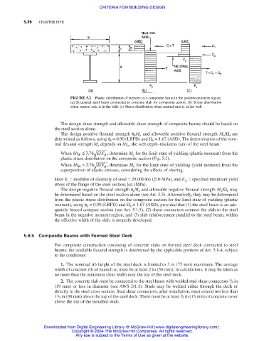
FIGURE 5.2 Plastic distribution of stresses in a composite beam in the positive-moment region.
(a) Structural steel beam connected to concrete slab for composite action. (b) Stress distribution
when neutral axis is in the slab. (c) Stress distribution when neutral axis is in the web.
The design shear strength and allowable shear strength of composite beams should be based on
the steel section alone.
The design positive flexural strength φ b M n and allowable positive flexural strength M n /Ω b are
determined as follows, using φ b = 0.90 (LRFD) and Ω b = 1.67 (ASD). The determination of the nom-
inal flexural strength M n depends on h/t w , the web depth–thickness ratio of the steel beam:
/
When ht/ W ≤ . 376 E F , determine M n for the limit state of yielding (plastic moment) from the
yf
plastic stress distribution on the composite section (Fig. 5.2).
When ht/ W > . 376 E F , determine M n for the limit state of yielding (yield moment) from the
/
yf
superposition of elastic stresses, considering the effects of shoring.
Here E s = modulus of elasticity of steel = 29,000 ksi (210 MPa), and F yf = specified minimum yield
stress of the flange of the steel section, ksi (MPa).
The design negative flexural strength φ b M n and allowable negative flexural strength M n /Ω b may
be determined based on the steel section alone (see Art. 5.5). Alternatively, they may be determined
from the plastic stress distribution on the composite section for the limit state of yielding (plastic
moment), using φ b = 0.90 (LRFD) and Ω b = 1.67 (ASD), provided that (1) the steel beam is an ade-
quately braced compact section (see Art. 5.1.5), (2) shear connectors connect the slab to the steel
beam in the negative moment region, and (3) slab reinforcement parallel to the steel beam, within
the effective width of the slab, is properly developed.
5.8.5 Composite Beams with Formed Steel Deck
For composite construction consisting of concrete slabs on formed steel deck connected to steel
beams, the available flexural strength is determined by the applicable portions of Art. 5.8.4, subject
to the conditions:
1. The nominal rib height of the steel deck is limited to 3 in (75 mm) maximum. The average
width of concrete rib or haunch w r must be at least 2 in (50 mm); in calculations, it may be taken as
no more than the minimum clear width near the top of the steel deck.
3
2. The concrete slab must be connected to the steel beam with welded stud shear connectors / 4 in
(19 mm) or less in diameter (see AWS D1.1). Studs may be welded either through the deck or
directly to the steel cross section. Stud shear connectors, after installation, must extend not less than
1
1
1 / 2 in (38 mm) above the top of the steel deck. There must be at least / 2 in (13 mm) of concrete cover
above the top of the installed studs.
Downloaded from Digital Engineering Library @ McGraw-Hill (www.digitalengineeringlibrary.com)
Copyright © 2004 The McGraw-Hill Companies. All rights reserved.
Any use is subject to the Terms of Use as given at the website.