
Page 52 - Structural Steel Designers Handbook AISC, AASHTO, AISI, ASTM, and ASCE-07 Design Standards
P. 52
Brockenbrough_Ch02.qxd 9/29/05 5:01 PM Page 2.14
FABRICATION AND ERECTION*
2.14 CHAPTER TWO
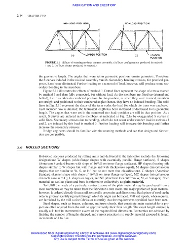
FIGURE 2.1 Effects of reaming methods on truss assembly. (a) Truss configurations produced in methods
1 and 2. (b) Truss shapes produced in method 3.
the geometric length. The angles that were set in geometric position remain geometric. Therefore,
the S curves induced in the no-load assembly vanish. Secondary bending stresses, for practical pur-
poses, have been eliminated. Further loading or a removal of load, however, will produce some sec-
ondary bending in the members.
Figure 2.1b illustrates the effects of method 3. Dotted lines represent the shape of a truss reamed
by method 3 and then fully connected, but without load. As the members are fitted up (pinned and
bolted), the truss takes its cambered position. In this position, as when they were reamed, members
are straight and positioned to their cambered angles; hence, they have no induced bending. The solid
lines in Fig. 2.1b represent the shape of the truss under the load for which the truss was cambered.
Each member now is strained; the fabricated length has been increased or decreased to its geometric
length. The angles that were set in the cambered (no-load) position are still in that position. As a
result, S curves are induced in the members, as indicated in Fig. 2.1b by exaggerated S curves in
solid lines. Secondary stresses due to bending, which do not occur under camber load in methods 1
and 2, are induced by this load in method 3. Further loading will increase this bending and further
increase the secondary stresses.
Bridge engineers should be familiar with the reaming methods and see that design and fabrica-
tion are compatible.
2.6 ROLLED SECTIONS
Hot-rolled sections produced by rolling mills and delivered to the fabricator include the following
designations: W shapes (wide-flange shapes with essentially parallel flange surfaces), S shapes
2
(American Standard beams with slope of 16 / 3% on inner flange surfaces), HP shapes (bearing-pile
shapes similar to W shapes but with flange and web thicknesses equal), M shapes (miscellaneous
shapes that are similar to W, S, or HP but do not meet that classification), C shapes (American
2
Standard channel shape with slope of 16 / 3% on inner flange surfaces), MC shapes (miscellaneous
channels similar to C), L shapes or angles, and ST (structural tees cut from W, M, or S shapes). Such
material, as well as plates and bars, is referred to collectively as plain material.
To fulfill the needs of a particular contract, some of the plain material may be purchased from a
local warehouse or may be taken from the fabricator’s own stock. The major portion of plain material,
however, is ordered directly from a mill to specific properties and dimensions. Each piece of steel on the
order is given an identifying mark through which its origin can be traced. Mill test reports, when required,
are furnished by the mill to the fabricator to certify that the requirements specified have been met.
Steel shapes, such as beams, columns, and truss chords, that constitute main material for a pro-
ject are often ordered from the mill to approximately their final length. The exact length ordered is
usually a 4- to 6-in increment in excess of the required final dimension. Economies are achieved by
limiting the number of lengths shipped, and current practice is to supply material grouped in length
increments of 4 to 6 in.
Downloaded from Digital Engineering Library @ McGraw-Hill (www.digitalengineeringlibrary.com)
Copyright © 2004 The McGraw-Hill Companies. All rights reserved.
Any use is subject to the Terms of Use as given at the website.