
Page 101 - Structural Steel Designers Handbook AISC, AASHTO, AISI, ASTM, and ASCE-07 Design Standards
P. 101
Brockenbrough_Ch03.qxd 9/29/05 5:05 PM Page 3.33
CONNECTIONS
CONNECTIONS 3.33
When required by plans and specifications, welded assemblies should be stress-relieved by heat
treating, but this is rarely required in building construction. (See AWS D1.1 for temperatures and
holding times required.) Finish machining should be done after stress relieving.
Tack and other temporary welds are subject to the same quality requirements as final welds. For
tack welds, however, preheat is not mandatory for single-pass welds that are remelted and incorpo-
rated into continuous submerged-arc welds. Also, defects such as undercut, unfilled craters, and
porosity need not be removed before final submerged-arc welding. Welds not incorporated into final
welds should be removed after they have served their purpose, and the surface should be made flush
with the original surface.
Before a weld is made over previously deposited weld metal, all slag should be removed, and the
weld and adjacent material should be brushed clean.
Groove welds should be terminated at the ends of a joint in a manner that will ensure sound welds.
Where possible, this should be done with the aid of weld tabs or runoff plates. AWS D1.1 does not
require removal of weld tabs for statically loaded structures but does require it for dynamically loaded
structures. The 2005 AISC Seismic Provisions also require their removal in zones of high seismicity.
The ends of the welds then should be made smooth and flush with the edges of the abutting parts.
After welds have been completed, slag should be removed from them. The metal should not be
painted until all welded joints have been completed, inspected, and accepted. Before paint is applied,
spatter, rust, loose scale, oil, and dirt should be removed.
AWS D1.1 presents details of acceptable techniques for welding in buildings. These techniques
include handling of electrodes and fluxes and maximum welding currents.
3.2.19 Weld Quality
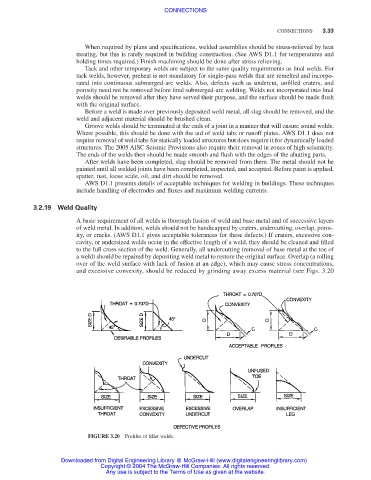
A basic requirement of all welds is thorough fusion of weld and base metal and of successive layers
of weld metal. In addition, welds should not be handicapped by craters, undercutting, overlap, poros-
ity, or cracks. (AWS D1.1 gives acceptable tolerances for these defects.) If craters, excessive con-
cavity, or undersized welds occur in the effective length of a weld, they should be cleaned and filled
to the full cross section of the weld. Generally, all undercutting (removal of base metal at the toe of
a weld) should be repaired by depositing weld metal to restore the original surface. Overlap (a rolling
over of the weld surface with lack of fusion at an edge), which may cause stress concentrations,
and excessive convexity, should be reduced by grinding away excess material (see Figs. 3.20
FIGURE 3.20 Profiles of fillet welds.
Downloaded from Digital Engineering Library @ McGraw-Hill (www.digitalengineeringlibrary.com)
Copyright © 2004 The McGraw-Hill Companies. All rights reserved.
Any use is subject to the Terms of Use as given at the website.