Page 190 - Structural Steel Designers Handbook AISC, AASHTO, AISI, ASTM, and ASCE-07 Design Standards
P. 190

Brockenbrough_Ch04.qxd  9/29/05  5:09 PM  Page 4.18


                                          BUILDING CODES, LOADS, AND FIRE PROTECTION*


                   4.18  CHAPTER FOUR

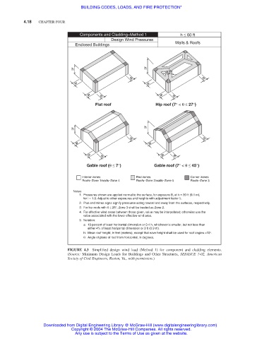
                                         Components and Cladding–Method 1        h ≤ 60 ft
                                                      Design Wind Pressures
                                       Enclosed Buildings                      Walls & Roofs


                                      h                            h
                                                                           a a
                                                             a                            a
                                       a                            a
                                                  a                           a
                                            a                            a
                                               Flat roof               Hip roof (7° < θ ≤ 27°)


                                      h                            h

                                                              a                           a
                                       a                            a

                                                  a                            a
                                            a                            a
                                            Gable roof (θ ≤ 7°)        Gable roof (7° < θ ≤ 45°)

                                          Interior zones        End zones            Corner zones
                                          Roofs–Zone 1/walls–Zone 4  Roofs–Zone 2/walls–Zone 5  Roofs–Zone 3
                                       Notes:
                                          1.  Pressures shown are applied normal to the surface, for exposure B, at h = 30 ft (9.1 m),
                                             for l = 1.0. Adjust to other exposures and heights with adjustment factor λ.
                                          2.  Plus and minus signs signify pressures acting toward and away from the surfaces, respectively.
                                          3.  For hip roofs with θ ≤ 25°, Zone 3 shall be treated as Zone 2.
                                          4.  For effective wind areas between those given, value may be interpolated; otherwise use the
                                             value associated with the lower effective wind area.
                                         5. Notation:
                                             a:   10 percent of least horizontal dimension or 0.4 h, whichever is smaller, but not less than
                                                  either 4% of least horizontal dimension or 3 ft (0.9 m).
                                             h:   Mean roof height, in feet (meters), except that eave height shall be used for roof angles <10°.
                                           θ:   Angle of plane of roof from horizontal, in degrees.

                                    FIGURE 4.3 Simplified design wind load (Method 1) for component and cladding elements.
                                    (Source:  Minimum Design Loads for Buildings and Other Structures, SEI/ASCE 7-02,  American
                                    Society of Civil Engineers, Reston, Va., with permission.)


                           Downloaded from Digital Engineering Library @ McGraw-Hill (www.digitalengineeringlibrary.com)
                                      Copyright © 2004 The McGraw-Hill Companies. All rights reserved.
                                       Any use is subject to the Terms of Use as given at the website.
   185   186   187   188   189   190   191   192   193   194   195