Page 224 - Structural Steel Designers Handbook AISC, AASHTO, AISI, ASTM, and ASCE-07 Design Standards
P. 224

Brockenbrough_Ch05.qxd  9/29/05  5:12 PM  Page 5.4


                                                 CRITERIA FOR BUILDING DESIGN


                   5.4  CHAPTER FIVE

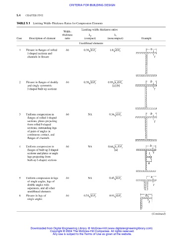
                   TABLE 5.1 Limiting Width–Thickness Ratios for Compression Elements
                                                        Limiting width–thickness ratios
                                             Width–
                                             thickness      λ ρ           λ r
                   Case   Description of element  ratio  (compact)    (noncompact)       Example
                                                      Unstiffened elements
                                                              /
                                                                            /
                                                                        .
                    1   Flexure in flanges of rolled   b/t  038 EF y    10 EF y
                                                          .
                         I-shaped sections and
                         channels in flexure


                                                          .
                    2   Flexure in flanges of doubly  b/t  038 EF y    095 kE /F L
                                                                       .
                                                              /
                                                                           c
                         and singly symmetric                            [a] [b]
                         I-shaped built-up sections


                    3   Uniform compression in  b/t        NA          056 EF y
                                                                            /
                                                                        .
                         flanges of rolled I-shaped
                         sections, plates projecting
                         from rolled I-shaped
                         sections; outstanding legs
                         of pairs of angles in
                         continuous contact, and
                         flanges of channels
                                                                       .
                    4   Uniform compression in  b/t        NA          064 kE /F y
                                                                           c
                         flanges of built-up I-shaped                     [a]
                         sections and plates or angle
                         legs projecting from
                         built-up I-shaped sections


                    5   Uniform compression in legs  b/t   NA          045 EF y
                                                                            /
                                                                        .
                         of single angles, legs of
                         double angles with
                         separators, and all other
                         unstiffened elements
                                                                            /
                    6   Flexure in legs of     b/t       054 EF y      091 EF y
                                                              /
                                                          .
                                                                        .
                         single angles
                                                                                               (Continued)


                           Downloaded from Digital Engineering Library @ McGraw-Hill (www.digitalengineeringlibrary.com)
                                      Copyright © 2004 The McGraw-Hill Companies. All rights reserved.
                                       Any use is subject to the Terms of Use as given at the website.
   219   220   221   222   223   224   225   226   227   228   229