
Page 370 - Structural Steel Designers Handbook AISC, AASHTO, AISI, ASTM, and ASCE-07 Design Standards
P. 370
Brockenbrough_Ch08.qxd 9/29/05 5:21 PM Page 8.24
LATERAL-FORCE DESIGN
8.24 CHAPTER EIGHT
have inherently less ductility than shallower sections. The research clearly demonstrated the impor-
tance of understanding the yield mechanisms and failure modes of the connection, and the balanc-
ing of these behaviors to achieve optimal performance
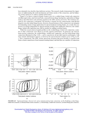
Figure 8.13a shows a typical moment–rotation curve for a welded-flange, bolted-web connection
with the tough welds, removed runoff tabs, removed bottom-flange backing bar, and reinforced flange
welds as described above and currently required in the AISC seismic provisions. The resistance pro-
vided by this connection is substantial. The ductility is limited, but the connection has some flexural
integrity even after initial flange fracture. However, the performance of this connection is not adequate
for demanding seismic design applications for special-moment-resisting frames. As a result, this con-
nection is no longer prequalified for special-moment-resisting frame application. However, the welded-
flange, bolted-web connection may still be suitable for ordinary-moment frames.
While the research showed significant flaws in the welded-flange, bolted-web connection, a num-
ber of other connections were shown to provide superior performance. In particular, the reduced-
beam-section connection, the welded-flange, welded-web connection, and the bolted-flange plate
connection (illustrated in Fig. 8.12b, c, and d, respectively) all provided superior performance, with
large inelastic deformation capacity as shown by the typical moment–rotation curves of Fig. 8.13b,
c, and d, respectively. The AISC seismic provisions recognize that great ductility is required from
beam–column connections of steel moment-resisting frames, and that there are a number of connections
30,000
20,000
1.5
Rotational 10,000
resistance
Beam moment M p −0.5 first fracture −10,000 0
1.0
remaining after
0.5
0.0
−1.0
−30,000
−1.5 −20,000
−0.04 −0.03 −0.02 −0.01 0 0.01 0.02 0.03 0.04 −0.04 −0.02 0 0.02 0.04
Total plastic rotation (radians) Total plastic rotation (radians)
(a) (b)
1.5 1.5
Beam moment M p −0.5 Normalized moment M/M ref −0.5
1.0
1.0
0.5
0.5
0.0
0.0
−1.0
−1.5 −1.0
−1.5
−0.04 −0.03 −0.02 −0.01 0 0.01 0.02 0.03 0.04 −8 −6 −4 −2 0 2 4 6 8
Total plastic rotation (radians) Total rotation (%)
(c) (d)
FIGURE 8.13 Typical performance observed with various moment-resisting frame connections. (a) Pre-Northridge welded-flange,
bolted-web connection. (b) Reduced-beam-section connection. (c) Welded-flange, welded-web connection. (d) Bolted-flange plate connection.
Downloaded from Digital Engineering Library @ McGraw-Hill (www.digitalengineeringlibrary.com)
Copyright © 2004 The McGraw-Hill Companies. All rights reserved.
Any use is subject to the Terms of Use as given at the website.