
Page 71 - Structural Steel Designers Handbook AISC, AASHTO, AISI, ASTM, and ASCE-07 Design Standards
P. 71
Brockenbrough_Ch03.qxd 9/29/05 5:05 PM Page 3.3
CONNECTIONS
CONNECTIONS 3.3
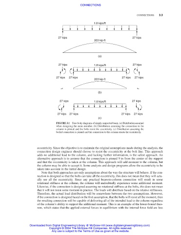
1.8 kips/ft
27 kips 27 kips
203 kip·ft
(a)
27 kips 1.8 kips/ft 27 kips
27 kips 27 kips 27 kips 27 kips
203 kip·ft
(b)
27 kips 1.8 kips/ft 27 kips
27 kips 27 kips 27 kips 27 kips
(c)
FIGURE 3.1 Free-body diagrams of simply supported beam. (a) Distribution assumed
when designing the main member. (b) Distribution assuming the connection to the
column is pinned and the bolts resist the eccentricity. (c) Distribution assuming the
bolted connection is pinned and the connection to the column resists the eccentricity.
eccentricity. Since the objective is to maintain the original assumptions made during the analysis, the
connection design engineer should choose to resist the eccentricity at the bolt line. This approach
adds no additional load to the column, and lacking further information, is the safest approach. An
alternative approach is to assume that the connection is pinned 9 in from the center of the support
and that the eccentricity is taken at the column. This approach will add moment to the column, but
the column may be able to accept it. Some analysis and design programs allow the eccentricity to be
taken into account in the initial design.
Note that both approaches are only assumptions about the way the structure will behave. If the con-
nection is designed so that the bolts can take all the eccentricity, this does not mean that they will actu-
ally see all the eccentricity. Since any practical beam-to-column connection will result in some
rotational stiffness at the column, the column will undoubtedly experience some additional moment.
Likewise, if the connection is designed assuming no rotational stiffness at the bolts, this does not mean
that it will not resist some moment in practice. The loads will distribute based on the relative stiffnesses.
Therefore, the actual load distribution will be somewhere between the two assumptions. However,
if the connection is designed based on the first assumption, that the bolts will resist all the moment, then
the resulting connection will be capable of delivering all of the intended load to the column regardless
of the column’s ability to support the additional moment. This is an example of the lower-bound theo-
rem, which states that the applied external forces in equilibrium with the internal force field are less
Downloaded from Digital Engineering Library @ McGraw-Hill (www.digitalengineeringlibrary.com)
Copyright © 2004 The McGraw-Hill Companies. All rights reserved.
Any use is subject to the Terms of Use as given at the website.