
Page 91 - Structural Steel Designers Handbook AISC, AASHTO, AISI, ASTM, and ASCE-07 Design Standards
P. 91
Brockenbrough_Ch03.qxd 9/29/05 5:05 PM Page 3.23
CONNECTIONS
CONNECTIONS 3.23
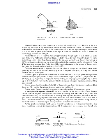
FIGURE 3.14 Fillet weld. (a) Theoretical cross section. (b) Actual
cross section.
Fillet welds have the general shape of an isosceles right triangle (Fig. 3.14). The size of the weld
is given by the length of leg. The strength is determined by the throat thickness, the shortest distance
from the root (intersection of legs) to the face of the weld. If the two legs are unequal, the nominal
size of the weld is given by the shorter of the legs. If welds are concave, the throat is diminished
accordingly, and so is the strength.
Fillet welds are used to join two surfaces approximately at right angles to each other. The joints
may be lap (Fig 3.15) or tee or corner (Fig 3.16). Fillet welds also may be used with groove welds
to reinforce corner joints. In a skewed tee joint, the included angle of weld deposit may vary up to
3
30° from the perpendicular, and one corner of the edge to be connected may be raised, up to / 16 in.
1
If the separation is greater than / 16 in, the weld leg must be increased by the amount of the root open-
ing. A further discussion of this is given in Art. 3.2.20.
Groove welds are made in a groove between the edges of two parts to be joined. These welds
generally are used to connect two plates lying in the same plane (butt joint), but they also may be
used for tee and corner joints.
Standard types of groove welds are named in accordance with the shape given the edges to be
welded: square, single V, double V, single bevel, double bevel, single U, double U, single J, and dou-
ble J (Fig. 3.17). Edges may be shaped by thermal cutting, arc-air gouging, or edge planing. Material
3
up to / 8 in thick, however, may be groove welded with square-cut edges, depending on the welding
process used.
Groove welds should extend the full width of the parts joined. Intermittent groove welds, and butt
joints not fully welded throughout the cross section, are prohibited.
Groove welds also are classified as complete-penetration and partial-penetration welds.
In a complete-joint-penetration weld, the weld material and the base metal are fused through-
out the depth of the joint. This type of weld is made by welding from both sides of the joint or from
one side to a backing bar. When the joint is made by welding from both sides, the root of the first-
pass weld is chipped or gouged to sound metal before the weld on the opposite side, or back pass, is
made. The throat dimension of a complete-joint-penetration groove weld, for stress computations, is
the full thickness of the thinner part joined, exclusive of weld reinforcement.
Partial-joint-penetration welds should be used when forces to be transferred are less than
those requiring a complete-joint-penetration weld. The edges may not be shaped over the full joint
FIGURE 3.15 Welded FIGURE 3.16 Welded joints. (a) Tee joint.
lap joint. (b) Corner joint.
Downloaded from Digital Engineering Library @ McGraw-Hill (www.digitalengineeringlibrary.com)
Copyright © 2004 The McGraw-Hill Companies. All rights reserved.
Any use is subject to the Terms of Use as given at the website.