
Page 316 - Sustainable On-Site CHP Systems Design, Construction, and Operations
P. 316
Sustaining Operational Ef ficiency of a CHP System 289
Efficiency/
Effectiveness
Component Purpose Relation Variables
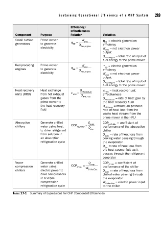
Small turbine Prime mover W elec η = electric generation
EE
generators to generate η = Q efficiency
EE
electricity Fuel,engine W = net electrical power
elec
output
Q = total rate of input of
Fuel,engine
fuel energy to the prime mover
Reciprocating Prime mover W elec η = electric generation
EE
engines to generate η = Q efficiency
EE
electricity Fuel,engine W = net electrical power
elec
output
Q = total rate of input of
Fuel.engine
fuel energy to the prime mover
Heat recovery Heat exchange ε = Q HRU,actual ε HRU = heat recover unit
units (HRU) from hot exhaust HRU Q effectiveness
gases from the HRU,max Q = rate of heat gain by
HRU,actual
prime mover to the heat recovery fluid
the heat recovery Q = maximum possible
HRU,max
fluid rate of heat loss from the
waste heat stream from the
prime mover in the HRU
Absorption Generate chilled = Q evap COP AbChiller = coefficient of
chillers water using heat COP AbChiller Q performance of the absorption
to drive refrigerant gen chiller
from solution in Q = rate of heat loss from
evap
an absorption cooling water passing through
refrigeration cycle the evaporator
Q = rate of heat loss from
gen
the heat source fluid as it
passes through the refrigerant
generator
Vapor- Generate chilled Q evap COP Chiller = coefficient of
compression water using COP Chiller = W performance of the chiller
chillers electric power to ChillerElec Q = rate of heat loss from
evap
drive compressors chilled water passing through
in a vapor- the evaporator
compression W = electric power input
ChillerElec
refrigeration cycle to the chiller
TABLE 17-1 Summary of Expressions for CHP Component Efficiencies