Page 269 -
P. 269

236     part 3  •  the analysis proCess

              Figure 9.1
                                              Data Flow Diagram                 Process Specification and Logic
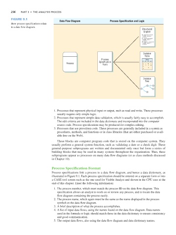
              How process specifications relate
              to a data flow diagram.
                                                                                                      Structured
                                                                                                       English
                                                                                                      IF construction
                                                                                                      THEN deduc
                                                                                                        ENDIF
                                                                                                      IF replacement
                                                                                                      THEN add  1
                                                                                                        ENDIF
                                                                                                      IF owner choose
                                                                                                      THEN add  1
                                                                                                        ENDIF
                                                                                                       Decision
                                                                                                        Table
                                                                           Process                       Rules
                                                                         Specification                  1'  2'  3'  4'
                                                   Process                  Form                       Y Y  N
                                                                                                       X  Y  Y X  N
                                                                                                       X

                                                                                                       Decision
                                                                                                        Tree

                                                                                                          20  Q  40
                                                                                                        P   T
                                                                                                      10      50
                                                                                                        X
                                                                                                          30


                                           1. Processes that represent physical input or output, such as read and write. These processes
                                             usually require only simple logic.
                                           2. Processes that represent simple data validation, which is usually fairly easy to accomplish.
                                             The edit criteria are included in the data dictionary and incorporated into the computer
                                             source code. Process specifications may be produced for complex editing.
                                           3. Processes that use prewritten code. These processes are generally included in a system as
                                             procedures, methods, and functions or in class libraries (that are either purchased or avail-
                                             able free on the Web).

                                             These blocks are computer program code that is stored on the computer system. They
                                         usually perform a general system function, such as validating a date or a check digit. These
                                         general-purpose subprograms are written and documented only once but form a series of
                                         building blocks that may be used in many systems throughout the organization. Thus, these
                                         subprograms appear as processes on many data flow diagrams (or as class methods discussed
                                         in Chapter 10).


                                         Process Specification Format
                                         Process specifications link a process to a data flow diagram, and hence a data dictionary, as
                                         illustrated in Figure 9.1. Each process specification should be entered on a separate form or into
                                         a CASE tool screen such as the one used for Visible Analyst and shown in the CPU case at the
                                         end of this chapter. Enter the following information:

                                           1. The process number, which must match the process ID on the data flow diagram. This
                                             specification allows an analyst to work on or review any process, and to locate the data
                                             flow diagram containing the process easily.
                                           2. The process name, which again must be the same as the name displayed in the process
                                             symbol on the data flow diagram.
                                           3. A brief description of what the process accomplishes.
                                           4. A list of input data flows, using the names found on the data flow diagram. Data names
                                             used in the formula or logic should match those in the data dictionary to ensure consistency
                                             and good communication.
                                           5. The output data flows, also using the data flow diagram and data dictionary names.
   264   265   266   267   268   269   270   271   272   273   274