Page 317 -
P. 317

284     Part 3  •  the analysis Process
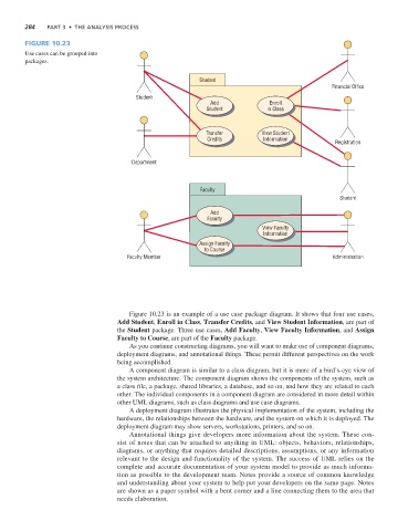
              Figure 10.23
              Use cases can be grouped into
              packages.

                                                                  Student
                                                                                                         Financial Office
                                               Student
                                                                     Add               Enroll
                                                                    Student           in Class


                                                                    Transfer        View Student
                                                                    Credits          Information
                                                                                                          Registration

                                              Department


                                                                  Faculty
                                                                                                            Student

                                                                     Add
                                                                    Faculty
                                                                                     View Faculty
                                                                                     Information
                                                                  Assign Faculty
                                                                   to Course
                                            Faculty Member                                                Administration


                                             Figure 10.23 is an example of a use case package diagram. It shows that four use cases,
                                         Add Student, Enroll in Class, Transfer Credits, and View Student Information, are part of
                                         the Student package. Three use cases, Add Faculty, View Faculty Information, and Assign
                                         Faculty to Course, are part of the Faculty package.
                                             As you continue constructing diagrams, you will want to make use of component diagrams,
                                         deployment diagrams, and annotational things. These permit different perspectives on the work
                                         being accomplished.
                                             A component diagram is similar to a class diagram, but it is more of a bird’s-eye view of
                                         the system architecture. The component diagram shows the components of the system, such as
                                         a class file, a package, shared libraries, a database, and so on, and how they are related to each
                                         other. The individual components in a component diagram are considered in more detail within
                                         other UML diagrams, such as class diagrams and use case diagrams.
                                             A deployment diagram illustrates the physical implementation of the system, including the
                                         hardware, the relationships between the hardware, and the system on which it is deployed. The
                                         deployment diagram may show servers, workstations, printers, and so on.
                                             Annotational things give developers more information about the system. These con-
                                         sist of notes that can be attached to anything in UML: objects, behaviors, relationships,
                                         diagrams, or anything that requires detailed descriptions, assumptions, or any information
                                         relevant to the design and functionality of the system. The success of UML relies on the
                                         complete and accurate documentation of your system model to provide as much informa-
                                         tion as possible to the development team. Notes provide a source of common knowledge
                                         and understanding about your system to help put your developers on the same page. Notes
                                         are shown as a paper symbol with a bent corner and a line connecting them to the area that
                                         needs elaboration.
   312   313   314   315   316   317   318   319   320   321   322