
Page 103 - Teach Yourself Electricity and Electronics
P. 103
Voltages across series resistances 83
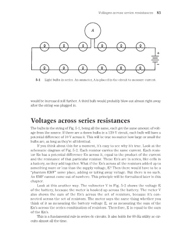
5-1 Light bulbs in series. An ammeter, A is placed in the circuit to measure current.
would be increased still further. A third bulb would probably blow out almost right away
after the string was plugged in.
Voltages across series resistances
The bulbs in the string of Fig. 5-1, being all the same, each get the same amount of volt-
age from the source. If there are a dozen bulbs in a 120-V circuit, each bulb will have a
potential difference of 10 V across it. This will be true no matter how large or small the
bulbs are, as long as they’re all identical.
If you think about this for a moment, it’s easy to see why it’s true. Look at the
schematic diagram of Fig. 5-2. Each resistor carries the same current. Each resis-
tor Rn has a potential difference En across it, equal to the product of the current
and the resistance of that particular resistor. These En’s are in series, like cells in
a battery, so they add together. What if the En’s across all the resistors added up to
something more or less than the supply voltage, E? Then there would have to be a
“phantom EMF” some place, adding or taking away voltage. But there is no such.
An EMF cannot come out of nowhere. This principle will be formalized later in this
chapter.
Look at this another way. The voltmeter V in Fig. 5-2 shows the voltage E
of the battery, because the meter is hooked up across the battery. The meter V
also shows the sum of the En’s across the set of resistors, because it’s con-
nected across the set of resistors. The meter says the same thing whether you
think of it as measuring the battery voltage E, or as measuring the sum of the
En’s across the series combination of resistors. Therefore, E is equal to the sum
of the En’s.
This is a fundamental rule in series dc circuits. It also holds for 60-Hz utility ac cir-
cuits almost all the time.