
Page 65 - Teach Yourself Electricity and Electronics
P. 65
Electromagnetic deflection 45
likely, when this effect was first observed, the scientist tried different arrangements to
see how much the compass needle could be displaced, and how small a current could
be detected. An attempt was made to obtain the greatest possible current-detecting
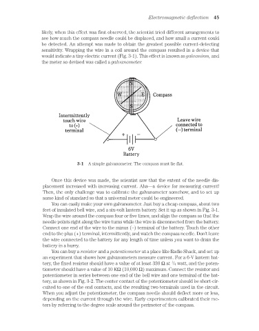
sensitivity. Wrapping the wire in a coil around the compass resulted in a device that
would indicate a tiny electric current (Fig. 3-1). This effect is known as galvanism, and
the meter so devised was called a galvanometer.
3-1 A simple galvanometer. The compass must lie flat.
Once this device was made, the scientist saw that the extent of the needle dis-
placement increased with increasing current. Aha—a device for measuring current!
Then, the only challenge was to calibrate the galvanometer somehow, and to set up
some kind of standard so that a universal meter could be engineered.
You can easily make your own galvanometer. Just buy a cheap compass, about two
feet of insulated bell wire, and a six-volt lantern battery. Set it up as shown in Fig. 3-1.
Wrap the wire around the compass four or five times, and align the compass so that the
needle points right along the wire turns while the wire is disconnected from the battery.
Connect one end of the wire to the minus (–) terminal of the battery. Touch the other
end to the plus (+) terminal, intermittently, and watch the compass needle. Don’t leave
the wire connected to the battery for any length of time unless you want to drain the
battery in a hurry.
You can buy a resistor and a potentiometer at a place like Radio Shack, and set up
an experiment that shows how galvanometers measure current. For a 6-V lantern bat-
1
tery, the fixed resistor should have a value of at least 330 Ω at /4 watt, and the poten-
tiometer should have a value of 10 KΩ (10,000 Ω) maximum. Connect the resistor and
potentiometer in series between one end of the bell wire and one terminal of the bat-
tery, as shown in Fig. 3-2. The center contact of the potentiometer should be short-cir-
cuited to one of the end contacts, and the resulting two terminals used in the circuit.
When you adjust the potentiometer, the compass needle should deflect more or less,
depending on the current through the wire. Early experimenters calibrated their me-
ters by referring to the degree scale around the perimeter of the compass.