
Page 88 - Teach Yourself Electricity and Electronics
P. 88
68 Basic dc circuits
Wiring diagrams
The difference between a schematic diagram and a wiring diagram is the amount of
detail included. In a schematic diagram, the interconnection of the components is
shown, but the actual values of the components are not necessarily indicated.
You might see a diagram of a two-transistor audio amplifier, for example, with re-
sistors and capacitors and coils and transistors, but without any data concerning the
values or ratings of the components. This is a schematic diagram, but not a true wiring
diagram. It gives the scheme for the circuit, but you can’t wire the circuit and make it
work, because there isn’t enough information.
Suppose you want to build the circuit. You go to an electronics store to get the
parts. What sizes of resistors should you buy? How about capacitors? What type of tran-
sistor will work best? Do you need to wind the coils yourself, or can you get them ready
made? Are there test points or other special terminals that should be installed for the
benefit of the technicians who might have to repair the amplifier? How many watts
should the potentiometers be able to handle? All these things are indicated in a wiring
diagram, a jazzed-up schematic. You might have seen this kind of diagram in the back of
the instruction manual for a hi-fi amp or an FM stereo tuner or a television set. Wiring
diagrams are especially useful and necessary when you must service or repair an elec-
tronic device.
Voltage/current/resistance circuit
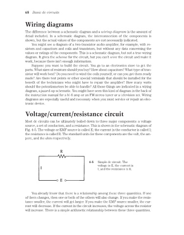
Most dc circuits can be ultimately boiled down to three major components: a voltage
source, a set of conductors, and a resistance. This is shown in the schematic diagram of
Fig. 4-5. The voltage or EMF source is called E; the current in the conductor is called I;
the resistance is called R. The standard units for these components are the volt, the am-
pere, and the ohm respectively.
4-5 Simple dc circuit. The
voltage is E, the current is
I, and the resistance is R.
You already know that there is a relationship among these three quantities. If one
of them changes, then one or both of the others will also change. If you make the resis-
tance smaller, the current will get larger. If you make the EMF source smaller, the cur-
rent will decrease. If the current in the circuit increases, the voltage across the resistor
will increase. There is a simple arithmetic relationship between these three quantities.