
Page 140 - The Art and Science of Analog Circuit Design
P. 140
Cari Battjes
^,
I PEAKIN G DISTRIBUTE D AMP L I F I E i
CAPACITANC E LOA D
INTERSTAT E PEA K I N
* BJU F I C I AJ.J_0 E L A Y y I H E / R
DELA Y (EQUALIZE R
SI6NA L LOO P THR U
< R CR T DISTRIBUTE D DEFLECTO R
{source or load)
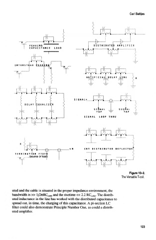
Figure 10-2.
The Versatile T-coil.
uted and the cable is situated in the proper impedance environment, the
bandwidth is » l/2itRC caWe and the risetime « 2.2 RC cable. The distrib-
uted inductance in the line has worked with the distributed capacitance to
spread out, in time, the charging of this capacitance. A pi-section LC
filter could also demonstrate Principle Number One, as could a distrib-
uted amplifier.
123