
Page 55 - The Combined Finite-Discrete Element Method
P. 55
38 PROCESSING OF CONTACT INTERACTION
Figure 2.1 Node to edge (left) and edge to edge (right) contact.
More general situations are handled by allowing node-to-line contact and, equivalently,
edge-to-edge, node-to-edge, node-to-node and node-to-surface contact (Figure 2.1). The
common feature of all algorithms that handle contact kinematics in this way are con-
centrated contact forces, as opposed to distributed contact force approaches, which are
usually based on the consideration of overlapping volumes.
Both the distributed and concentrated approaches involve relatively complicated kine-
matics of contact with many branches of code, in which case processing of kinematics of
contact can be on the critical path of the otherwise efficient solution.
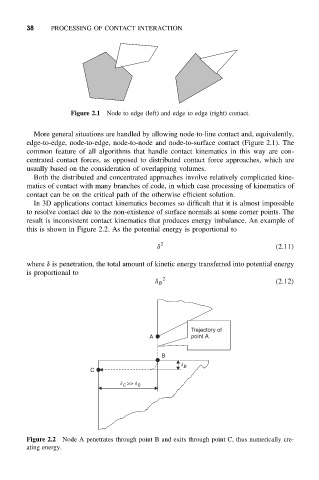
In 3D applications contact kinematics becomes so difficult that it is almost impossible
to resolve contact due to the non-existence of surface normals at some corner points. The
result is inconsistent contact kinematics that produces energy imbalance. An example of
this is shown in Figure 2.2. As the potential energy is proportional to
δ 2 (2.11)
where δ is penetration, the total amount of kinetic energy transferred into potential energy
is proportional to
2
δ B (2.12)
Trajectory of
A point A
B
d B
C
d C >> d B
Figure 2.2 Node A penetrates through point B and exits through point C, thus numerically cre-
ating energy.