
Page 255 - The Jet Engine
P. 255
Power plant installation
3. The position of the power plant must not affect
the efficiency of the air intake, and the exhaust gases
must be discharged clear of the aircraft and its
control surfaces. Any installation must also be such
that it produces the minimum drag effect.
4. Power plant installations are numbered from left
to right when viewed from the rear of the aircraft.
5. Supersonic aircraft usually have the power plants
buried in the aircraft for aerodynamic reasons.
Vertical lift aircraft can use either the buried installa-
tion or the podded power plant, or in some instances
both types may be combined in one aircraft (Part 18).
AIR INTAKES
6. The main requirement of an air intake is that,
under all operating conditions, delivery of-the air to
the engine is achieved with the minimum loss of
energy occurring through the duct. To enable the
compressor to operate satisfactorily, the air must Fig. 23-4 Pitot-type intake.
reach the compressor at a uniform pressure
distributed evenly across the whole inlet area.
is approached, the efficiency of this type of air intake
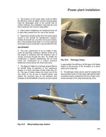
7. The ideal air intake for a turbo-jet engine fitted to begins to fall because of the formation of a shock
an aircraft flying at subsonic or low supersonic wave at the intake lip.
speeds, is a short, pitot-type circular intake (fig. 23-
4). This type of intake makes the fullest use of the 8. The pitot-type intake can be used for engines that
ram effect on the air due to forward speed, and are mounted in pods or in the wings, although the latter
suffers the minimum loss of ram pressure with sometimes require a departure from the circular cross-
changes of aircraft attitude. However, as sonic speed section because of the wing thickness (fig. 23-5).
Fig. 23-5 Wing leading edge intakes.
245