
Page 223 - Thomson, William Tyrrell-Theory of Vibration with Applications-Taylor _ Francis (2010)
P. 223
210 Lagrange’s Equation Chap. 7
Solution: There are two translational modes, and Q2, and each of the four corners can
rotate independently, making a total of six generalized coordinates, ^ B y
allowing each of these displacements to take place with all others equal to zero, the
displacement of the frame can be seen to be the superposition of the six generalized
coordinates.
Example 7.1-3
In defining the motion of a framed structure, the number of coordinates chosen often
exceeds the number of degrees of freedom of the system so that constraint equations
are involved. It is then desirable to express all of the coordinates u in terms of the
fewer generalized coordinates ^ by a matrix equation of the form
u = Cq
The generalized coordinates q can be chosen arbitrarily from the coordinates u.
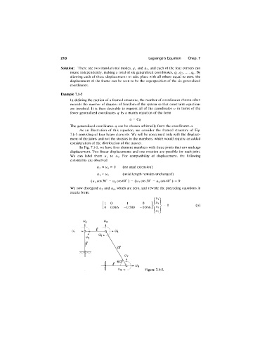
As an illustration of this equation, we consider the framed structure of Fig.
7.1-5 consisting of four beam elements. We will be concerned only with the displace
ment of the joints and not the stresses in the members, which would require an added
consideration of the distribution of the masses.
In Fig. 7.1-5, we have four element members with three joints that can undergo
displacement. Two linear displacements and one rotation are possible for each joint.
j
We can label them W to iiy. For compatibility of displacement, the following
constraints are observed
U2 = = 0 (no axial extension)
j
W = (axial length remains unchanged)
(1/4 cos 30° - W5 cos 60° ) - (u-j cos 30° - cos 60° ) = 0
We now disregard U2 and which are zero, and rewrite the preceding equations in
matrix form:
1 0 - 1 0 = 0
0 0.866 -0.500 -0.866 (a)
Figure 7.1-5.