
Page 228 - Thermal Hydraulics Aspects of Liquid Metal Cooled Nuclear Reactors
P. 228
Subchannel analysis for LMR 199
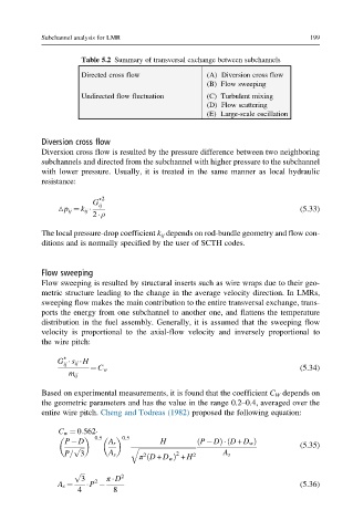
Table 5.2 Summary of transversal exchange between subchannels
Directed cross flow (A) Diversion cross flow
(B) Flow sweeping
Undirected flow fluctuation (C) Turbulent mixing
(D) Flow scattering
(E) Large-scale oscillation
Diversion cross flow
Diversion cross flow is resulted by the pressure difference between two neighboring
subchannels and directed from the subchannel with higher pressure to the subchannel
with lower pressure. Usually, it is treated in the same manner as local hydraulic
resistance:
G ∗ 2
ij
△p ij ¼ k ij (5.33)
2 ρ
The local pressure-drop coefficient k ij depends on rod-bundle geometry and flow con-
ditions and is normally specified by the user of SCTH codes.
Flow sweeping
Flow sweeping is resulted by structural inserts such as wire wraps due to their geo-
metric structure leading to the change in the average velocity direction. In LMRs,
sweeping flow makes the main contribution to the entire transversal exchange, trans-
ports the energy from one subchannel to another one, and flattens the temperature
distribution in the fuel assembly. Generally, it is assumed that the sweeping flow
velocity is proportional to the axial-flow velocity and inversely proportional to
the wire pitch:
∗
G s ij H
ij
¼ C w (5.34)
m ij
Based on experimental measurements, it is found that the coefficient C W depends on
the geometric parameters and has the value in the range 0.2–0.4, averaged over the
entire wire pitch. Cheng and Todreas (1982) proposed the following equation:
C w ¼ 0:562
0:5 0:5
P D A r H ð P DÞ D + D w Þ
ð
p ffiffiffi q ffiffiffiffiffiffiffiffiffiffiffiffiffiffiffiffiffiffiffiffiffiffiffiffiffiffiffiffiffiffiffiffiffiffi (5.35)
P= 3 A s 2 2 2 A s
π D + D w Þ + H
ð
p ffiffiffi
3 2 π D 2
A s ¼ P (5.36)
4 8