
Page 125 - Bird R.B. Transport phenomena
P. 125
110 Chapter 3 The Equations of Change for Isothermal Systems
stream just outside the vessel. Show that this leads to an (a) Show that the velocity profile for the system is given by
efflux velocity i; = \/2gh. This is known as Torricelli's
efflux - 2MB 2 i (y (A\ii* - i \
equation. v = ———-— -^ £ - ^— (3B.16-1)
(2P n
To get this result, one has to assume incompressibility x fiL A\B e* - 1 /
(which is usually reasonable for most liquids), and that the
height of the fluid surface is changing so slowly with time in which A = BV OP/JJL.
that the Bernoulli equation can be applied at any instant of (b) Show that the mass flow rate in the x direction is
time (the quasi-steady-state assumption). p - V L)B Wp i i
3
_ (3B.16-2)
3B.15 Shape of free surface in tangential annular flow. A\2 A e A - \ )
(a) A liquid is in the annular space between two vertical (c) Verify that the above results simplify to those of Prob-
cylinders of radii KR and R, and the liquid is open to the lem 2B.3 in the limit that there is no cross flow at all (that
atmosphere at the top. Show that when the inner cylinder is, A -> 0).
rotates with an angular velocity Ц, and the outer cylinder (d) A colleague has also solved this problem, but taking a
is fixed, the free liquid surface has the shape coordinate system with у = 0 at the midplane of the slit,
with the porous walls located at у = ±b. His answer to
part (a) above is
in which z R is the height of the liquid at the outer-cylinder v x _ e ar) - j] sinh a - cosh a (3B.16-3)
x
wall, and £ = r/R. (v ) (1 /a) sinh a - cosh a
(b) Repeat (a) but with the inner cylinder fixed and the in which a = bv p/iJL and 17 = y/b. Is this result equivalent
o
outer cylinder rotating with an angular velocity \. Show to Eq. 3B.16-1?
i
that the shape of the liquid surface is
3C.1 Parallel-disk compression viscometer 6 (Fig. 3C.-1).
two
circular
l K 2 R
z z - l [(Г 2 - 1) + 4K- 2 In ( - K~\? - 1)] A fluid fills completely the region is between and the upper
disks
of radius R. The bottom disk
fixed,
ZR — Z — -r— I
(3B.15-2) disk is made to approach the lower one very slowly with a
constant speed v , starting from a height H (and H « R).
o
0
o
(c) Draw a sketch comparing these two liquid-surface The instantaneous height of the upper disk is Hit). It is de-
shapes. sired to find the force needed to maintain the speed v .
0
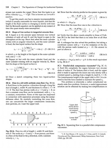
3B.16 Flow in a slit with uniform cross flow (Fig. 3B.16). This problem is inherently a rather complicated un-
A fluid flows in the positive x-direction through a long flat steady-state flow problem. However, a useful approximate
duct of length L, width W, and thickness B, where L » W solution can be obtained by making two simplifications in
» B. The duct has porous walls at у = 0 and у = В, so
that a constant cross flow can be maintained, with v y = v , Fit)
0
a constant, everywhere. Flows of this type are important
in connection with separation processes using the sweep-
diffusion effect. By carefully controlling the cross flow,
one can concentrate the larger constituents (molecules, > - ^
dust particles, etc.) near the upper wall.
Upper disk I
moves down- '
ward slowly 1
at constant 1
• • • • • • • • speed i; 0 ^ + -
:y = H(t)
Lower disk |
Г
is fixed I K-H
t t t t t t t t t Fig. 3C.1. Squeezing flow in a parallel-disk compression
L viscometer.
Fig. 3B.16. Flow in a slit of length L, width W, and thick-
ness B. The walls at у = 0 and у = В are porous, and there 6 J. R. Van Wazer, J. W. Lyons, K. Y. Kim, and R. E. Colwell,
is a flow of the fluid in the у direction, with a uniform Viscosity and Flow Measurement, Wiley-Interscience, New York
velocity v = v . (1963), pp. 292-295.
y 0