
Page 157 - Trenchless Technology Piping Installation and Inspection
P. 157
Pipe and Pipe Installation Considerations 123
Rigid Flexible
Concrete pipe Steel pipe
Vitrified clay pipe Ductile iron pipe
Prestressed concrete cylinder pipe Polyvinyl chloride pipe
Reinforced concrete pipe Polyethylene pipe
Bar-wrapped concrete cylinder pipe Fiberglass reinforced plastic pipe
Asbestos-cement pipe Acrylonitrile-butadiene styrene pipe
Fiber-cement pipe
TABLE 4.2 Examples of Rigid and Flexible Pipes
surrounding the pipe. Typical examples of rigid pipes are clay pipes
and concrete pipes. On the other hand, flexible pipes are capable of
deforming (without damage to the pipe) to the extent that the passive
resistance of soils on the sides is mobilized providing additional sup-
port. ASTM standards define flexible pipes as pipes that deflect more
than 2 percent of their diameter without any sign of structural failure.
Typical examples include ductile iron, high density polyethylene
pipe (HDPE), steel, and polyvinyl chloride (PVC) pipes. Common
terminology used to characterize properties of rigid and flexible pipes
is strength and stiffness. While strength refers to the ability of rigid
pipes in resisting loads and resulting stress in the pipe materials,
stiffness refers to the ability of flexible pipes in resisting deflection.
Pipes that overlap these two categories are sometimes referred to
as semirigid, semiflexible. or intermediate pipes. However, such dis-
tinction is seldom made in current design standards (Moser and
Folkman, 2008). Examples of different types of rigid and flexible
pipes are given in Table 4.2.
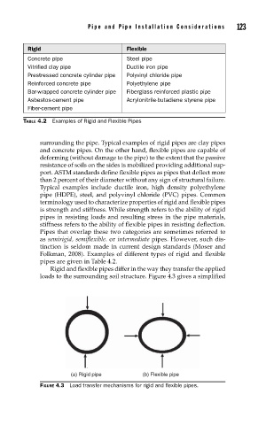
Rigid and flexible pipes differ in the way they transfer the applied
loads to the surrounding soil structure. Figure 4.3 gives a simplified
(a) Rigid pipe (b) Flexible pipe
FIGURE 4.3 Load transfer mechanisms for rigid and fl exible pipes.