
Page 254 - Tribology in Machine Design
P. 254
Friction, lubrication and wear in higher kinematic pairs 239
Eliminating Q gives
This is Reynolds equation for a steady two-dimensional flow in a thin
lubricating film. Given the variation in thickness of the film h(x), it can be
integrated to give pressure p(x) developed by hydrodynamic action. For a
more complete discussion of the Reynolds equation the reader is referred to
the books on lubrication listed at the end of Chapter 5.
Now, eqn (6.18) will be used to find the pressure developed in a film
between two rotating cylinders.
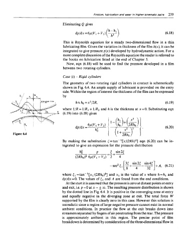
The geometry of two rotating rigid cylinders in contact is schematically
shown in Fig. 6.4. An ample supply of lubricant is provided on the entry
side. Within the region of interest the thickness of the film can be expressed
by
where l/R = 1/Rt + l/R 2 and h is the thickness at x=0. Substituting eqn
(6.19) into (6.18) gives
Figure 6.4
l
By making the substitution c=tan [x/(2Rh)*] eqn (6.20) can be in-
tegrated to give an expression for the pressure distribution
i
where ^=tan [xi/(2Rh 0)*'] and x t is the value of x where h = h v and
dp/dx=0. The values of ^ and A are found from the end conditions.
At the start it is assumed that the pressure is zero at distant points at entry
and exit, i.e. p=0atx=±oo. The resulting pressure distribution is shown
by the dotted line in Fig. 6.4. It is positive in the converging zone at entry
and equally negative in the diverging zone at exit. The total force W
supported by the film is clearly zero in this case. However this solution is
unrealistic since a region of large negative pressure cannot exist in normal
ambient conditions. In practice the flow at the exit breaks down into
streamers separated by fingers of air penetrating from the rear. The pressure
is approximately ambient in this region. The precise point of film
breakdown is determined by consideration of the three-dimensional flow in