
Page 270 - Tribology in Machine Design
P. 270
Rolling-contact bearings 255
point in either of the support bodies
Equation (7.22) may also be applied to roller-bearings. It is seen from eqn
(7.22), for line contact, that the radius of curvature of the roller does not
affect the deflection.
From the equations describing the elastic deflection of two bodies in
contact it is apparent that their normal approach depends on the normal
load, the geometry, and certain material constants. The calculation of
deflections in a complete bearing requires a knowledge of its geometry,
material and the radial and axial components of the load. From the load
Figure 7.9 components, the load on the most heavily loaded rolling element must be
calculated. Exact calculations of deflection are complex and tedious.
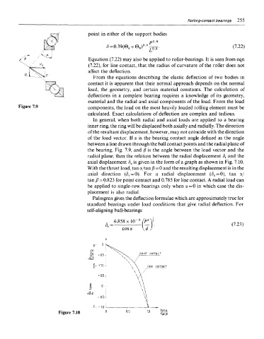
In general, when both radial and axial loads are applied to a bearing
inner ring, the ring will be displaced both axially and radially. The direction
of the resultant displacement, however, may not coincide with the direction
of the load vector. If a is the bearing contact angle defined as the angle
between a line drawn through the ball contact points and the radial plane of
the bearing, Fig. 7.9, and /? is the angle between the load vector and the
radial plane, then the relation between the radial displacement <5 r and the
axial displacement (5 a is given in the form of a graph as shown in Fig. 7.10.
With the thrust load, tan a/tan /?=0 and the resulting displacement is in the
axial direction (3 r — Q). For a radial displacement (<) a = 0), tan a/
tan /? = 0.823 for point contact and 0.785 for line contact. A radial load can
be applied to single-row bearings only when a=0 in which case the dis-
placement is also radial.
Palmgren gives the deflection formulae which are approximately true for
standard bearings under load conditions that give radial deflection. For
self-aligning ball-bearings
Figure 7.10