
Page 153 - Troubleshooting Analog Circuits
P. 153
140 I I. Dealing with References and Regulators
could damage transistors, wires, fuses, circuit breakers, reputations, and power com-
panies. A soft-start circuit forces the switcher to bring the output up to its working
levels gradually, and draws only a finite amount of current from the mains as it does.
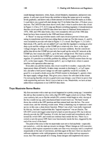
I could show you a good soft-start design, but I’ll do better than that-I’ll show you a
bud one. The LM3524 data sheet shows (well, that’s what it used to show) the circuit
in Figure 11.2 for a 15 V, 0.5 A step-up (Boost) switching regulator. (I should mention
that this circuit and the LM3524 data sheet have been in National Semiconductor’s
1978,1980, and 1982 data books; they were mistakenly left out of the 1986 data
book but have been restored to the 1989 and future editions.)
A “Boost” or step-up switcher needs a soft-start circuit to prevent it from satu-
rating its transformer and from just sitting there at start-up. For this reason, Cl and D,
were included to provide soft-start in Figure 11.2’s circuit. But Figure 1 1.2 is still a
bad circuit, if R, and D2 are not added! Let’s say that the regulator is running at a low
duty-cycle and the voltage on the COW pin is relatively low. Now, as the input
voltage changes, the duty cycle may have to increase suddenly. But the control am-
plifier that drives the COMP pin not only has to pull up the series RC network at the
COW pin, but it must also pull C1 up to the new voltage level. This load is unfairly
heavy, too much for the COMP pin’s control amp, and the output will be slow to
regulate. It’s possible to avoid this problem by adding a 470 kR resistor from the top
of C, to the input supply. This resistor pulls CI up to a high level, where it cannot
interfere with operation after start-up.
Even after you add the resistor, this circuit would be in trouble-specially if the
input power shuts off briefly. It takes many seconds to discharge C1, a 5 pF capac-
itor, and after a brief power outage no soft-start capability would be available. A
good fix is to install a diode across the 470 kR resistor to discharge Cl quickly when
the input supply voltage drops. This gives you a chance for soft-start on the restart.
I’m not saying that this circuit is a good worst-case design-you’d have to prove that
with engineering and tests. But it’s not as bad as it was. Meanwhile, we have at least
added these components to our LM3524 data sheet.
Toys Illustrate Some Basics
My first encounter with a start-up circuit happened at a pretty young age. I remember
the old toy that resided in a box with a big ON-OFF toggle switch on its front. When
your curiosity led you to flip the switch ON, a motor would begin to whir, the top of
the box would rise up, and a mechanical hand would reach out. The hand would
throw the switch to the OFF position and then retreat back into the box. The cover
would close, and the whirring would cease. What a charming way to represent a start-
up (or, in this case, a shut-down) function. When I was a kid, I was really impressed
by this toy, but later I realized that this “logical sequencer” was an illusion. The
ON-OFF switch did mgger some kind of a latch to turn the power ON, but it did not
directly provide the OFF function. If it did, the hand would stall immediately after it
turned the switch OFF, and would not continue back inside the box. There WJUS a
switch to turn the power OFF, but it was functionally inside the box, triggered by the
end of the travel of the hand.
The point of the story is that we must make sure not to fool anybody--especially
not ourselves-with the start-up circuits we design. When I design an A/D converter,
I include a shift-register sequencer to make sure that every necessary task is completed
sequentially at the start of conversion, and then again at the end. I have no idea how
software engineers write valid programs to make sure no false start-up sequences
occur, but I bet some people do it wrong. Some designs still implement the micro-