
Page 196 - Troubleshooting Analog Circuits
P. 196
Back to Electronic Circuits . . I83
7- 32v FEEDBACK
UNREGULATED 4 L1
-
-
'r LM2575-5.0 OUTPUT
2 0 +5V @In
REGULATED
DI +-&-JUT OUTPUT
NOTE PIN NMERS ARE
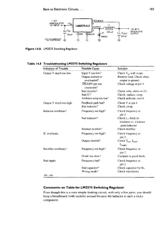
Figure 14.8. LM2575 Switching Regulator.
Table 14.8 Troubleshooting LM2575 Switching Regulators
Indication of Trouble Possible Cause Solution
Output V much too low. Input V too low? Check Vi" with scope.
Output shorted or Remove load. Check ohms.
overloaded?
- output to ground.
ON/OFF pin not Check voltage at pin 5.
connected?
Bad rectifier? Check volts, ohms on D1.
Bad IC? Check, replace, swap.
Ambient temp too hot? Check ambient, cool it.
Output V much too high. Feedback path bad? Check V at pin 4.
Bad inductor? Check, swap.
Inductor overheats? Frequency too high? Check frequency at
pin 2.
Bad inductor? Check L, check its
lossiness vs. a known
good inductor.
Shorted rectifier? Check rectifier.
IC overheats. Frequency too high? Check frequency at
pin 2.
Output shorted? Check vo,, . Iload.
ISUpplY.
Rectifier overheats? Frequency too high? Check frequency at
pin 2.
Diode too slow? Compare to good diode.
Bad ripple. Frequency bad? Check frequency at
pin 2.
Bad capacitor? Check capacitor for Rs.
Wrong mode? Check waveforms.
etc.. etc.
Comments on Table for LM2575 Switching Regulator
Even though this is a very simple-looking circuit, with only a few parts, you should
keep a breadboard (with sockets) around because the inductor is such a tricky
component.