
Page 49 - Troubleshooting Analog Circuits
P. 49
36 3. Getting Down to the Component Level
core temperature increases to a point where the core’s magnetic properties change
irreversibly. Regardless of the mechanism that caused the damage, you may have to
do as I once did-package the inductors with a strongly worded tag to demand that
nobody test them at Incoming Inspection.
Bob Widlar had a good solution to that. He would instruct the Incoming Inspection
Technician to count the number of leads. Don’t measure anything, just count the
number of leads. If they follow that instruction, they probably won’t wreck the trans-
former.
If you choose too small a wire size for your windings, the wire losses will be ex-
cessive. You can measure the winding resistance with an ohmmeter, or you can mea-
sure the wire’s thickness. But if the number of turns is wrong, you can best spot the
error with an L meter-remember that L N2. Be careful when using an ohmmeter
to make measurements on transformers and inductors-some ohmmeters put out so
many milliamps that they are likely to saturate the component you are trying to mea-
sure and at least temporarily alter its characteristics. Select an ohmmeter which puts
out only a small amount of current.
Protect Transistors from Voltage Kick
There is one trouble you can have with an inductor or relay coil that will not do any
harm to the magnetic device, but will leave a trail of death and destruction among its
associated components: When you use a transistor to draw a lot of current through an
inductor and then turn the transistor off, the “kick” from the inductor can generate a
A0 QC
0
PRIMARY SECONDARY
BO OD
N, Nz
N- 3
NZ
Rp - PRIMARY RESISTANCE
4 - PRIMARY LEAKAGE INDUCTANCE
Cp - PRIMARY DISTRIBUTED CAPACITANCE
- MUTUAL INDUCTANCE (REFLECTED TO PRIMARY)
R, - CORE LOSS
NW. - SECONDARY RESISTANCE (REFLECTED To PRIMARW
*‘L;-SECONDARY LEAKAGE INDUCTANCE (REFLECTED fo PRIMARY)
C@ - SECONDARY DISTRIBUTED CAPACITANCE (REFLECTED TO PRIMARY)
C, * PRIMARY-TOSECONDARY INTERWINDINQ CAPACITANCE
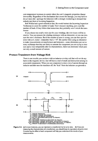
Figure 3.5. (a) In most instances, you can represent a transformer by its turns ratio. (b) If you are
measuring the characteristics of a transformer, you should keep its equivalent circuit in mind.
Considering the effect of each component will help you understand the results of your
measurements.