
Page 57 - Troubleshooting Analog Circuits
P. 57
44 4. Getting Down to the Component Level: Capacitor Problems
erly attenuate ripple. Another consequence of excessive ESR is the overheating and
failing of capacitorwapacitors may be passive components, but they are not trivial.
Not only does extended-foil construction lower a capacitor’s ESR, it also lowers
the component’s inductance. As a friend, Martin Giles, pointed out, after reading a
draft of my troubleshooting text, “Pease, you understand things really well if they are
at DC or just a little bit faster than DC.” I replied, “Well, that’s true, but what’s your
point?” His point was that in RF circuits, and many other kinds of fast circuits, you
should use capacitors and other components dressed closely together, so that the
inductance is small and well controlled. He is absolutely right-the layout of a high-
speed, fast-settling or a high-frequency circuit greatly affects its performance.
Capacitors for such circuits must be compact and not have long leads. Ceramic and
silvered-mica capacitors are often used for that reason.
Every year, billions of ceramic capacitors find their way into electronic products of
all kinds. There are basically three classes of these parts: the “high-K’ and “stable-K”
types and the COG or NPO types.
The high-K types, such as those with a “Z5U” characteristic, give you a lot of
capacitance in a small space-for example, lo6 pF in a 0.3-in. square that is 0.15-in.
thick. That’s the good news. The bad news is that the capacitance of parts with this
Z5U characteristic drops 20% below the room-temperature value at 0 and 55 “C; it
drops 60% below the room-temperature value at -25 and +90 “C. Also, the dielectric
has a poor dissipation factor, mediocre leakage, and a mediocre voltage coefficient of
capacitance. Still, none of these drawbacks prevents capacitors of this type from
being used as bypass capacitors across the supply terminals of virtually every digital
IC in the whole world. That’s a lot of capacitors!
These ceramic capacitors have a feature that is both an advantage and a
drawback-a typical ESR of 0.1 Cl or lower. So, when a digital IC tries to draw a
50-mA surge of current for a couple of nanoseconds, the low ESR is a good feature:
It helps to prevent spikes on the power-supply bus. To get good bypassing and low
inductance you must, of course, install the ceramic capacitors with minimum lead
length. However, when you have 10 ICs in a row and 10 ceramic bypass capacitors,
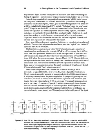
you’ve got a long LC resonator (Figure 4.2) with the power-supply bus acting as a
low-loss inductor between each pair of bypass capacitors. When repetitive pulses
excite this resonator, ringing of rather large amplitude can build up and cause an
excessively noisy power-supply bus. This can be especially troublesome if the signal
nn- Etc.
-
Etc.
Figure 4.2. Low ESR in a decoupling capacitor is a two-edged sword. Though a capacitor with low ESR
stabilizes the supply bus when the ICs draw short-duration current spikes, the low dissipation
factor encourages ringing by allowing the decoupling capacitance to resonate with the bus
inductance. One good cure is to place electrolytic capacitors, such as CI, across the bus. Cl’s
ESR of approximately I Cl damps the ringing.